LED lamp

A technology for LED lamps and LED power supplies, which is applied to the loss prevention measures of lighting devices, cooling/heating devices of lighting devices, lighting and heating equipment, etc. Problems such as poor heat dissipation effect of LED lamps

Inactive Publication Date: 2016-09-07
黄超
View PDF0 Cites 4 Cited by
  • Summary
  • Abstract
  • Description
  • Claims
  • Application Information

AI Technical Summary

Problems solved by technology

[0002] In the current prior art, LED lamps include a shell, an LED luminous body, a cover and an LED power supply. The LED luminous body is composed of a heat-conducting substrate and LED chips arranged on the heat-conducting substrate. The shell is made of metal material. The surface is equipped with sheet-like heat dissipation fins, and the heat dissipation fins are erected on the surface area of ​​the shell. The LED luminous body and LED power supply are arranged in the sealed cavity of the shell. The existing problem is that a large amount of heat generated by the LED luminous body accumulates in the shell In the chamber, the hot air in the sealed chamber cannot be discharged, and there is no way to achieve air convection heat exchange. The LED luminous body produces a heat island effect and light decays, which reduces the life of the LED lamp; the LED lamp conducts the heat generated by the LED luminous body to the shell. , and then dissipate heat through the vertical sheet-shaped cooling fins on the shell, the shape of the vertical sheet-shaped cooling fins is simple, resulting in poor cooling effect of LED lamps and unattractive appearance

Method used


Image

  • LED lamp
  • LED lamp
  • LED lamp

Examples


Embodiment Construction

[0020] The present invention will be further described below in conjunction with the accompanying drawings.

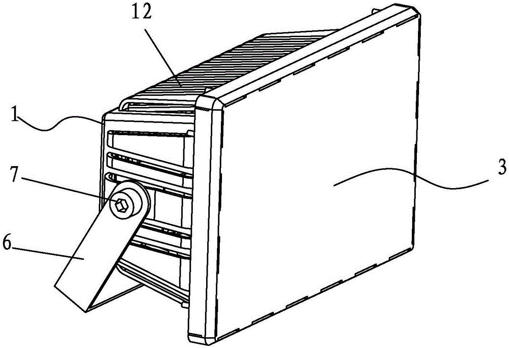
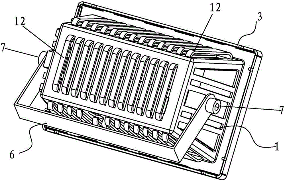
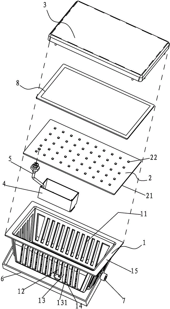
[0021] Such as figure 1 , figure 2 with Figure 4 As shown, an LED lamp includes a housing 1, an LED illuminant 2, a cover 3, an LED power supply 4 and a power connection wire 5, the cover 3 is provided with a lens, and the LED illuminant 2 is made of a heat-conducting substrate 21 and LED chips 22 arranged on the heat-conducting substrate, the housing 1 is integrally formed of metal materials, and the housing 1 is in the shape of a hollow cube to form a heat dissipation and radiation chamber 11; the LED power supply 4 is fixed on Power is supplied to the LED chip 22 in the heat dissipation radiation chamber 11, one end of the power connection line 5 is connected to the LED power supply 4, and the other end is connected to the LED illuminant 2;

[0022] Such as image 3 As shown, several heat dissipation holes 12 are arranged on the surface of the housing 1, and h...


PUM


Abstract

The invention discloses a LED lamp comprising a housing, a LED illuminant, a surface cover, a LED power supply and a power supply connecting line. The surface cover is provided with a lens; the LED illuminant is formed by a heat conducting substrate and LED chips; the housing is made of metal material by integral formation; the housing is hollow to form a heat dissipation chamber; the LED power supply is fixed inside the heat dissipation chamber of the housing and used for powering the LED chips; multiple heat dissipation holes are distributed in the surface of the housing, heat dissipation fins are installed at the right front or right rear of the openings of the heat dissipation holes, the openings of the heat dissipation holes are covered by the board bodies of the heat dissipation fins, two ends of the heat dissipation fins bend and are connected with the surface of the heat dissipation housing, two heat dissipation side holes are formed by the heat dissipation fins and the heat dissipation housing, and hot air can flows and dissipates through the heat dissipation side holes; the upper opening of the housing is provided with flanges which is fitted with the heat conducting substrate for heat conduction; the LED illuminant is connected with the housing. By means of the structure, the LED lamp has good heat dissipation effect and long service life.

Description

technical field [0001] The invention relates to the technical field of lamps, in particular to an LED lamp. Background technique [0002] In the current prior art, LED lamps include a shell, an LED luminous body, a cover and an LED power supply. The LED luminous body is composed of a heat-conducting substrate and LED chips arranged on the heat-conducting substrate. The shell is made of metal material. The surface is equipped with sheet-like heat dissipation fins, and the heat dissipation fins are erected on the surface area of ​​the shell. The LED luminous body and LED power supply are arranged in the sealed cavity of the shell. The existing problem is that a large amount of heat generated by the LED luminous body accumulates in the shell In the chamber, the hot air in the sealed chamber cannot be discharged, and there is no way to achieve air convection heat exchange. The LED luminous body produces a heat island effect and light decays, which reduces the life of the LED lam...

Claims


Application Information

Patent Timeline
Patent Type & Authority Applications(China)
IPC IPC(8): F21S8/00F21V29/83F21V29/76F21V31/00F21V29/503F21V15/01F21Y115/10
CPCF21S8/00F21V15/01F21V29/503F21V29/763F21V29/83F21V31/005
Inventor 黄超
Owner 黄超
Why Eureka
Try Eureka