
A shielded cable connector

A technology of shielding cables and cables, applied in the direction of connection, circuit, electrical components, etc., can solve the problems of difficult to achieve dustproof and waterproof, unable to shield, leakage and other problems

Active Publication Date: 2019-03-08
BEISIT ELECTRIC TECH HANGZHOU CO LTD
View PDF6 Cites 1 Cited by
  • Summary
  • Abstract
  • Description
  • Claims
  • Application Information

AI Technical Summary

Problems solved by technology

However, the current shielded joints usually use clamping claws to clamp the cables. Due to the large gap between the clamping claws, the cables will be stuck in the claws, which will affect the installation of the cables, and it is easy to scratch the skin of the cables, resulting in leakage. Danger
[0003] In order to protect the outer surface of the cable, the protective tube is usually placed outside the cable. However, although the traditional protective tube joint can be connected with the protective tube, it is difficult to achieve the effect of dustproof and waterproof, and it cannot prevent the electromagnetic waves generated by the cable. It plays a shielding role, but the shielding joint that can shield electromagnetic effects cannot be connected with the protective tube

Method used


Image

  • A shielded cable connector

Examples


Embodiment Construction

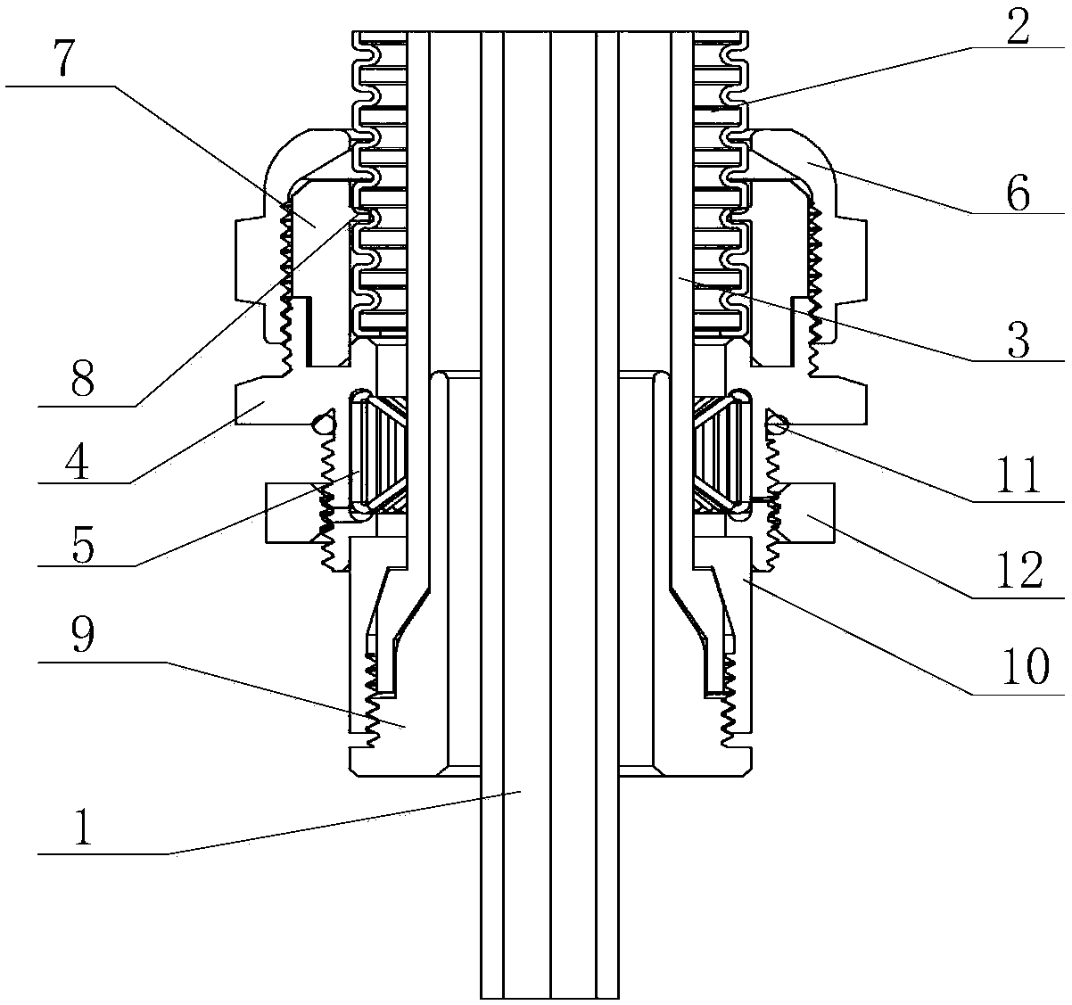
[0026] Based on the above research, the embodiment of the present invention provides a shielded cable joint, which can realize the connection of the protection tube and can achieve the effects of dustproof, waterproof and electromagnetic shielding.

[0027] In order to make the above objects, features and advantages of the present invention more comprehensible, the specific implementation manners of the present invention will be described in detail below in conjunction with the accompanying drawings.

[0028] In the following description, specific details are set forth in order to provide a thorough understanding of the present invention. However, the present invention can be implemented in many other ways than those described here, and those skilled in the art can make similar extensions without departing from the connotation of the present invention. Accordingly, the present invention is not limited to the specific embodiments disclosed below.

[0029] Please refer to figu...


PUM


Abstract

The invention discloses a shielded cable connector. The shielded cable connector comprises a protecting tube, a connector body, a fastening screw cap and a waterproof ring, wherein the protecting tube sleeves a cable, a shielding net is arranged in the protecting tube, and the shielding net extends to the exterior of the protecting tube axially; a through hole is arranged in the middle of the connector body, a shielding spring is arranged in the through hole of the connector body, and the inner side of the shielding spring is attached to the outer sidewall of the shielding net; the fastening screw cap is connected to a first end of the connector body through a screw thread; the bottom of the waterproof ring is connected to the first end of the connector body, the waterproof ring is arranged in the fastening screw cap, and the inner sidewall of the waterproof ring is closely attached to the outer sidewall of the protecting tube. The protecting tube sleeves the cable, so that the cable is protected. Through the fastening screw cap, the inner sidewall of the waterproof ring is closely attached to the outer wall of the protecting tube, so that the dustproof and waterproof effect is played, and meanwhile, the inner side of the shielding spring in the connect body is attached to the outer sidewall of the shielding net, the electromagnetic wave generated by the shielding cable can be shielded to prevent from affecting the human body and other electrical elements.

Description

technical field [0001] The invention relates to the field of cable joints, in particular to a shielded cable joint. Background technique [0002] In the field of power systems, cables are usually connected by cable joints, so as to increase the length of the cables and avoid the risk of leakage due to the exposed connection of the cables. In order to shield the electromagnetic waves generated when the cable is energized, it is usually connected through a shielded joint to prevent electromagnetic radiation from affecting the human body and other electrical components. However, the current shielded joints usually use clamping claws to clamp the cables. Due to the large gap between the clamping claws, the cables will be stuck in the claws, which will affect the installation of the cables, and it is easy to scratch the skin of the cables, resulting in leakage. Danger. [0003] In order to protect the outer surface of the cable, the protective tube is usually placed outside the...

Claims


Application Information

Patent Timeline
Patent Type & Authority Patents(China)
IPC IPC(8): H01R13/502H01R13/52H01R13/622H01R13/6581
CPCH01R13/502H01R13/5202H01R13/5205H01R13/5219H01R13/622H01R13/6581
Inventor 曾凡乐李小强曾浩沈炳杰
Owner BEISIT ELECTRIC TECH HANGZHOU CO LTD
Learn More