Coiled-material feeding mechanism of antenna terminal automatic laminating machine

An antenna terminal and feeding mechanism technology, applied in antenna connectors, circuit/collector parts, electrical components, etc., can solve the problem of affecting the service life and performance of products, and the technical requirements of workers' assembly are relatively high, affecting production efficiency and Product quality and other issues, to achieve good cutting and bending effect, reduce production costs, and reduce workpiece wear

Active Publication Date: 2016-09-07
ZHONGSHAN XINSHENG ELECTRIC APPLIANCE
View PDF7 Cites 5 Cited by
  • Summary
  • Abstract
  • Description
  • Claims
  • Application Information

AI Technical Summary

Problems solved by technology

[0002] At present, the antennas in computers, mobile phones, and tablet computers are composed of wire ends and terminals. However, the coil feeding mechanism of the existing antenna terminal automatic pressing machine has complex structure, low efficiency, low precision, unstable operation, and large Mass assembly line production is done manually by workers, which is prone to assembly problems, and the production process has relatively high requirements for workers' assembly skills. Once workers flow and change, it will affect production efficiency and product quality, and directly affect the service life of products. In view of this, it is necessary to improve the coil feeding mechanism of the existing antenna terminal automatic pressing machine

Method used


Image

  • Coiled-material feeding mechanism of antenna terminal automatic laminating machine
  • Coiled-material feeding mechanism of antenna terminal automatic laminating machine
  • Coiled-material feeding mechanism of antenna terminal automatic laminating machine

Examples


Embodiment Construction

[0020] The preferred embodiments of the present invention will be described in detail below in conjunction with the accompanying drawings, so that the advantages and features of the invention can be more easily understood by those skilled in the art, so as to define the protection scope of the present invention more clearly.

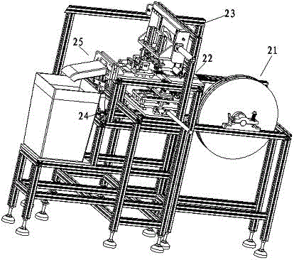
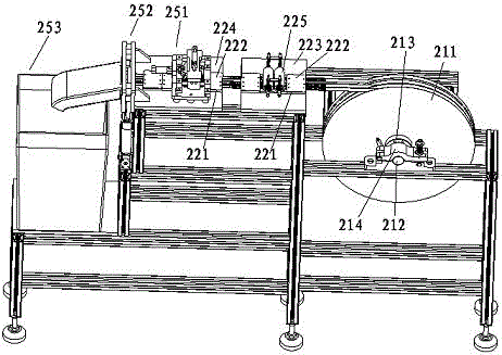
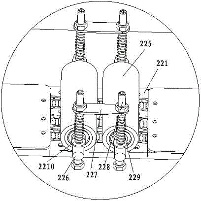
[0021] refer to Figure 1 to Figure 3 , a coil feeding mechanism of an automatic antenna terminal pressing machine, the coil feeding mechanism of the antenna terminal automatic pressing machine includes a coil feeding device 21, a coil straightening device 22, a coil cutting and bending device 23, Coil material stamping device 24 and waste material cutting and collecting device 25, coil material feeding device 21 and coil material straightening device 22 are arranged on the frame in sequence, and coil material cutting and bending device 23 is located on the frame above coil material straightening device 22 Above, the coil material stamping device 24 is l...


PUM


Abstract

The invention discloses a coiled-material feeding mechanism of an antenna terminal automatic laminating machine. The coiled-material feeding mechanism of the antenna terminal automatic laminating machine comprises a coiled-material feeding apparatus, a coiled-material correcting apparatus, a coiled-material cutting and bending apparatus, a coiled-material stamping apparatus and a waste material cutting and collecting apparatus, wherein the coiled-material feeding apparatus and the coiled-material correcting apparatus are arranged on a rack in sequence; the coiled-material cutting and bending apparatus is positioned on the rack above the coiled-material correcting apparatus; the coiled-material stamping apparatus is positioned on the rack below the coiled-material correcting apparatus; the coiled-material feeding apparatus comprises a material tray, a stepped shaft, a locking ring and a flange holder; the material tray passes through the stepped shaft to be fixed on the stepped shaft through the locking ring; and the two ends of the stepped shaft are fixed on the rack through the flange holder. By adoption of the mode, the coiled-material feeding mechanism is convenient to operate, long in service life, good in bending and stamping effect, low in workpiece abrasion, and capable of improving the production efficiency and lowering the production cost.

Description

technical field [0001] The invention relates to the field of mechanical automation, in particular to a coil material feeding mechanism of an antenna terminal automatic pressing machine. Background technique [0002] At present, the antennas in computers, mobile phones, and tablet computers are composed of wire ends and terminals. However, the coil feeding mechanism of the existing antenna terminal automatic pressing machine has complex structure, low efficiency, low precision, unstable operation, and large Mass assembly line production is done manually by workers, which is prone to assembly problems, and the production process has relatively high requirements for workers' assembly skills. Once workers flow and change, it will affect production efficiency and product quality, and directly affect the service life of products. In view of this, it is necessary to improve the coil feeding mechanism of the existing antenna terminal automatic pressing machine. Contents of the inv...

Claims


Application Information

Patent Timeline
Patent Type & Authority Applications(China)
IPC IPC(8): H01R43/048B21F23/00B21F1/00B21F1/02B21F11/00
CPCB21F1/00B21F1/026B21F23/00H01R43/048H01R2201/02
Inventor 鲍常莲
Owner ZHONGSHAN XINSHENG ELECTRIC APPLIANCE
Why Eureka
Try Eureka