Stable motor

A stable and stable stator technology, applied in the direction of electrical components, electromechanical devices, electric components, etc., can solve the problems of poor structure of the outer stator, stator and rotor, affect the working performance of motor parts, damage the electronic components of the circuit board, etc., and achieve the purpose of shortening the stay Effects of time, compactness, and volume reduction

Active Publication Date: 2016-09-07
佛山市顺德区乐普达电机有限公司
View PDF7 Cites 2 Cited by
  • Summary
  • Abstract
  • Description
  • Claims
  • Application Information

AI Technical Summary

Problems solved by technology

During the operation of the motor, a large current is injected into the coil of the stator, so that the coil generates a large amount of heat, and the heat generated continues to accumulate with the growth of time in the future, which makes the temperature inside the motor gradually increase, thus affecting the internal parts of the motor. Working performance also has a great impact on the service life of each part, especially the impact on the circuit board is more obvious, it is easier to damage the electronic components on the circuit board, and even cause the circuit board to burn out
Some existing motors with heat dissipation structure are only suitable for motors with inner stator and outer rotor structure, and the effect is not good for the structure of outer stator stator and rotor

Method used


Image

  • Stable motor
  • Stable motor

Examples


Embodiment 1

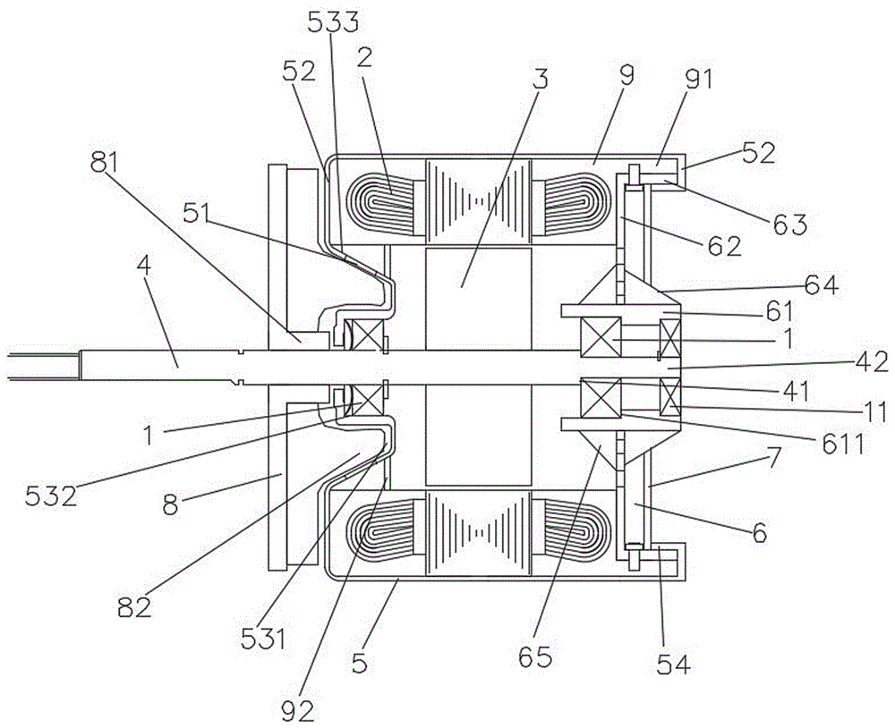
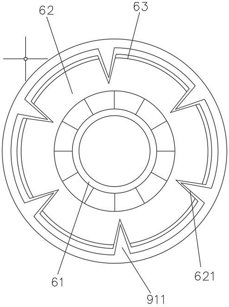
[0030] A stable motor, including a stator 2, a rotor 3 sleeved in the stator, a rotating shaft 4 pierced on the rotor, and a shell with a vent hole 51 on the end face 53 of the shell sleeved on the stator that is adapted to each other The body 5 and the center are provided with a base 6 for positioning and mounting holes 61, and a circuit board 7 is set up on the outside of the base, and a drainage fan 8 is fixed on the outside of the end surface of the shell on the rotating shaft, and a plastic seal is placed on the outside of the stator. Body 9, the end surface of the plastic package facing the base side is integrally provided with a ring of plastic sealing reinforcing connection ring 91 which is attached to the side wall of the housing, and the rear end of the housing extends backward and toward the direction of the rotating shaft Turn over to form a fixed riveting pressure limit flap 52 pressed against the end face of the plastic-sealed reinforced connection ring. The seat...

Embodiment 2

[0037] The difference from the above-mentioned embodiment is that there are several uniform force supporting reinforcing plates 65 connected to the seat plate evenly distributed on the part of the outer peripheral surface of the positioning installation hole column located in the motor.

[0038] The positioning truncated cone is a partially hollowed out truncated cone composed of several inclined strips formed by the partial tilting of the seat plate body to the rear end. The inclined strips are fixed to the rear end of the inclined strips and sleeved on the positioning installation Collar connection on hole post.

[0039] Uniformly supporting the reinforcing plate and the inclined strip improve the torsional strength of the positioning installation hole column from both ends, and ensure the stability of the connection between the rotating shaft and the bearing at this end. And the inclined strip is directly formed by the positioning cone with high strength and convenient proc...

Embodiment 3

[0041] The difference from the above embodiment is that the plastic-encapsulated reinforcing connection ring is a discontinuous ring composed of uniformly distributed plastic-encapsulated protrusions of the fan ring, the seat edge is a plurality of discontinuous edges corresponding to the fan ring, and the plastic-encapsulated reinforcement Locking bolts are also threaded between the connecting ring and the seat edge.


PUM


Abstract

The invention relates to the field of motors, and in particular relates to a stable motor. The stable motor comprises a stator, a rotor sleeved in the stator and a rotating shaft arranged on the rotor in a penetrating manner, and also comprises a shell and a base which are fit with each other, wherein the shell is sleeved on the stator and provided with vent holes in the shell end face, the base is provided with a locating mounting hole column at the center, a circuit board is erected on the outer side of the base, a draught fan is fixedly arranged on rotating shaft on the outer side of the shell end face, the stator is packaged with a plastic package body, and a circle of plastic package reinforced connecting ring arranged close to the side wall of the shell is integrally connected on the end face of the plastic package body facing the base side. Air flows at the rear end of the circuit board are sent into the motor via vent holes in the circuit board and base plate, in the same way, the air flows between the circuit board and base plate are sent into the motor via the vent holes in the base plate, then absorb heat in the motor, and then are rapidly exported from the motor via vent holes in the inclined reinforced pored groove wall. The whole motor is strong in integrality, compact in structure, convenient to dismount, low in cost, high in strength, good in stability and low in noise.

Description

technical field [0001] The invention relates to the field of motors, in particular to a stable motor. Background technique [0002] At present, motors are widely used in electronics and automation equipment industries. During the operation of the motor, a large current is injected into the coil of the stator, so that the coil generates a large amount of heat, and the heat generated continues to accumulate with the growth of time in the future, making the temperature inside the motor gradually increase, thus affecting the internal parts of the motor. Working performance also has a great impact on the service life of each part, especially the impact on the circuit board is more obvious, it is easier to damage the electronic components on the circuit board, and even cause the circuit board to burn out. Existing motors with heat dissipation structures are only suitable for motors with inner stator and outer rotor structures, and are not effective for outer stator stator and rot...

Claims


Application Information

Patent Timeline
Patent Type & Authority Applications(China)
IPC IPC(8): H02K9/06H02K5/20
CPCH02K5/04H02K5/16H02K5/20H02K9/06
Inventor 孙文鸿孙远
Owner 佛山市顺德区乐普达电机有限公司
Why Eureka
Try Eureka