Device for turbulence reduction

a technology of turbulence reduction and device, which is applied in the direction of sedimentation separation, sedimentation settling tank feed/discharge, and sedimentation separation, etc. it can solve the problems of large, turbulent eddies, reduced quality of liquid overflow, and inefficient use of settling area, so as to reduce the momentum, velocity, or even eliminate large-scale turbulent eddies. , the effect of simple design

Active Publication Date: 2015-05-05
BOARD OF SUPERVISORS OF LOUISIANA STATE UNIV & AGRI & MECHANICAL COLLEGE
View PDF28 Cites 45 Cited by
  • Summary
  • Abstract
  • Description
  • Claims
  • Application Information

AI Technical Summary

Benefits of technology

[0026]We have discovered a novel device for substantially reducing the momentum, velocity, or both of a first liquid that is flowing into a second liquid. The device allows one to substantially reduce or even eliminate large-scale turbulent eddies that could otherwise be produced by liquid flowing into or within a vessel. The invention employs a simple design, improves separation efficiencies, and requires only short residence times. The equipment footprint may be small. The invention is economical to employ, and it may readily be retrofitted onto existing equipment.
[0027]The direction of flow makes substantial changes several times after the fluid exits an inlet pipe or hose. Suitably-sized and positioned plates and baffles induce changes of flow direction. By the time the fluid leaves the interior of the device, the fluid velocity and momentum are both very low, and turbulence is nearly or entirely eliminated. In some cases, we have reduced flow velocity by a factor of ˜50. The novel device is simple to manufacture, to operate, and to clean.
[0028]Several of the devices may be placed simultaneously at different locations within a single clarifier, and thus increase efficiency further. The several devices are preferably uniformly distributed, and are preferably connected to a common header or input.
[0030]Adjacent to, and preferably affixed to the second plate are at least four deflection baffles, each of which is more-or-less perpendicular to the second plate, is more-or-less parallel to original direction of flow, and is more-or-less perpendicular to the local direction of the outward radial flow induced by the second plate. The baffles may be arranged in various configurations, e.g., a square, a hexagon, or a generally circular configuration. The baffles further divert the outward radial flow through a direction between about 90 degrees and about 180 degrees. (It is preferred to have spaces between adjacent baffles, as such spaces help inhibit the formation of vortices.) The combined effect of the second (deflection) plate and the baffles dissipates most of the energy of the flow within the space between the two parallel plates. Turbulent eddies are substantially reduced or even eliminated. Velocity and momentum of the fluid flow are greatly reduced—by a factor of 40, 50, or even higher. The device allows fluid to be introduced into a second liquid in vessel in a non-turbulent manner, at substantially higher rates than would otherwise be possible. (The first and second liquids may be the same or different.)

Problems solved by technology

Existing clarifier designs have the general disadvantage that large, turbulent eddies are created as liquid flows into the tanks.
The turbulence results in inefficient use of the settling area, reduced quality of the liquid overflow, and generally imposes longer residence times than would otherwise be needed.
A longer residence time is inherently less efficient and more expensive, especially where perishable or degradable products are involved.
For example, in the clarifying sugar juice, a longer residence time can result in partial product deterioration.
The horizontal flow reduces efficiency and throughput: It creates a large-scale, circular motion inside the clarifier, which decreases performance and separation efficiency.
A separation that takes only a few minutes on a small scale can take from 30 minutes to several hours in a mill due to the effects of turbulence on settling time.
Both computer modeling and experimental visualization have demonstrated that most existing clarifier designs are inefficient, and are subject to large-scale turbulence.
These inefficiencies lead to increased production costs, lower quality output, or both.
Some prior clarifier designs have employed multiple plates to increase settling area and to reduce eddies, but these designs have typically been too expensive and complex for widespread commercial use.
Even so, large-scale eddies can still be created in these devices due to the large mass of flow entering the clarifier.
Other design alternatives have not been widely accepted in the sugar industry.
Some recent clarifier designs are more efficient, with reduced residence times. However, these newer designs are more expensive; their installation would require most mills to purchase new equipment or to pay for costly re-engineering.
They typically produce lateral flows that can create large eddies that interfere with settling.
Significant issues for a lamella clarifier include the removal of solids and cleaning of the lamellae.
The cost for a lamella clarifier can be significant, especially if it is constructed from a non-polymeric material.
(Polymers can be difficult to use with high temperature sugar solutions.)

Method used


Image

  • Device for turbulence reduction
  • Device for turbulence reduction

Examples


example 1

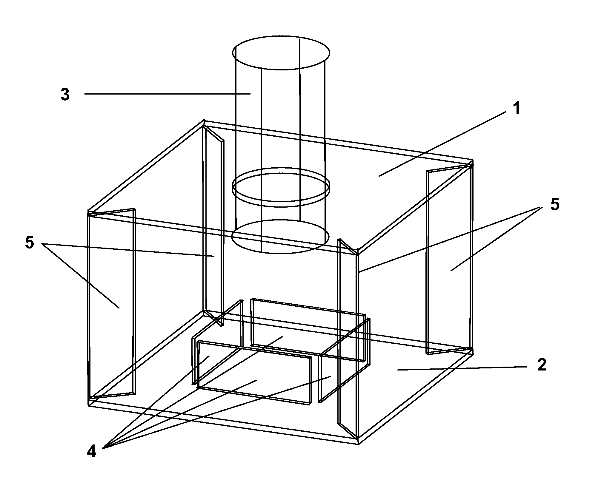
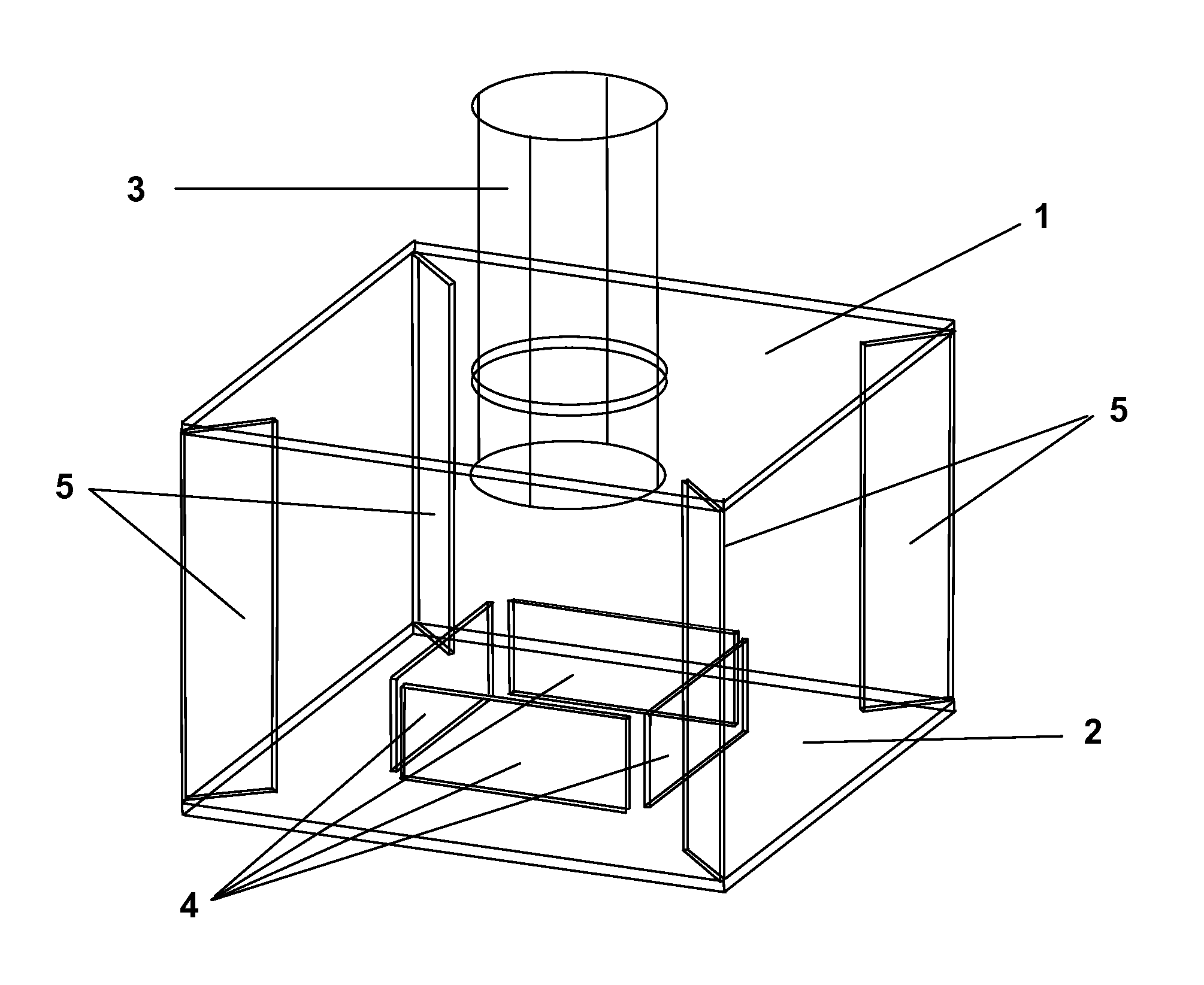
[0033]The FIGURE schematically depicts a prototype embodiment of the invention that has been successfully built and tested. This embodiment comprised two parallel, horizontal plates 1 and 2, with a feed pipe 3 extending vertically and perpendicularly through an opening in upper plate 1. The degree of turbulence was reduced substantially as lower plate 2 changed the flow direction and dissipated the energy of an impinging liquid jet. Baffles 4 further deflected the fluid flow, further dissipating energy. Spacers 5 held plates 1 and 2 in a fixed position relative to one another. Spacers 5 may also, depending on their configuration, secondarily dissipate additional energy from the fluid flow, although these effects are generally minimal because most of the energy has been dissipated before the liquid flow encounters the spacers.

[0034]Alternatively, the feed pipe may be positioned horizontally, parallel to the horizontal plates, for example if available space in a retrofit operation doe...

example 2

[0036]Testing of the prototype embodiment of Example 1, using dye in water, confirmed the non-turbulent dispersal of inflowing liquid into the tank, and in particular has confirmed that turbulence is reduced very substantially as compared to that seen from conventional flow from a simple pipe into a tank, without any turbulence reduction device. Water with dye was pumped through an 8 cm diameter hose at a rate of 23 m3 / h into a tank (volume ˜1 m3) containing water without dye. The test was repeated both with and without the prototype device attached to the end of the hose. Visualization of the resulting flow pattern showed substantial turbulence when the hose was used alone. In sharp contrast, there was almost a complete lack turbulence when the prototype device was attached to the hose. The surface of the water remained calm, despite the discharged of liquid at a rate of 23 m3 / h only ˜40 cm below the surface.

[0037]The novel device practically eliminated the horizontal component of ...

example 3

[0038]The novel device has been successfully implemented and tested in an industrial setting. An existing Graver clarifier in a Louisiana sugar mill was retrofitted with novel turbulence reduction devices in accordance with the present invention. The clarifier had a diameter of 6 m and a height of 7.5 m, including the conical bottom portion. The conventional trays were removed from the Graver clarifier, and overflow collection launders were installed and carefully leveled. Nine turbulence reduction devices, each generally similar to the device of Example 1, were positioned uniformly about 1.5 m above the bottom of the tank. A pre-distributor piping system divided the incoming liquid evenly among the nine turbulence reduction devices. Turbidity of the overflow liquid was measured using a Hach turbidimeter. The retrofit clarifier operated throughout the grinding season, with the exception of some mechanical shutdowns. The retrofit clarifier was one of three clarifiers run in parallel ...


PUM

PropertyMeasurementUnit
distanceaaaaaaaaaa
lengthaaaaaaaaaa
distanceaaaaaaaaaa

Abstract

Apparatus is disclosed for substantially reducing the momentum, velocity, or both of a first liquid that is flowing into a second liquid. The device allows one to substantially reduce or even eliminate large-scale turbulent eddies that could otherwise be produced by liquid flowing into or within a vessel, for example in a clarifier. Suitably-sized and positioned plates and baffles induce changes of flow direction in a limited volume. By the time the fluid leaves this volume, the fluid velocity is low, and turbulence is nearly or entirely eliminated. Several of the devices may be placed at different inputs within a single clarifier, and thus increase efficiency further.

Description

[0001]This is the United States national stage of international application PCT / US2010 / 049450, international filing date Sep. 20, 2010, which claims the benefit of the Sep. 23, 2009 filing date of U.S. provisional patent application Ser. No. 61 / 244,947 under 35 U.S.C. §119(e).TECHNICAL FIELD[0002]This invention pertains to an apparatus for reducing the momentum, velocity, or both of a turbulent liquid, for example in a clarifier.BACKGROUND ART[0003]“Clarification” is the settling or removal of suspended solids from a liquid, for example in municipal water treatment, the treatment of sugar cane juice, or the manufacture of pulp and paper. Existing clarifier designs have the general disadvantage that large, turbulent eddies are created as liquid flows into the tanks. The turbulence results in inefficient use of the settling area, reduced quality of the liquid overflow, and generally imposes longer residence times than would otherwise be needed. A longer residence time is inherently le...

Claims


Application Information

Patent Timeline
Patent Type & Authority Patents(United States)
IPC IPC(8): B01D21/24C13B20/16B01D21/00
CPCB01D21/0087C13B20/16B01D21/2416B01D21/2427Y10T137/0318
Inventor KOCHERGIN, VADIMGAUDET, CY
Owner BOARD OF SUPERVISORS OF LOUISIANA STATE UNIV & AGRI & MECHANICAL COLLEGE
Why Eureka
Try Eureka