Device for Turbulence Reduction
a technology of turbulence reduction and device, which is applied in the direction of sedimentation settling tank, separation process, filtration separation, etc., can solve the problems of large, turbulent eddies, reduced quality of liquid overflow, and inefficient use of settling area, so as to reduce the momentum, velocity, or even eliminate large-scale turbulent eddies, simple design
- Summary
- Abstract
- Description
- Claims
- Application Information
AI Technical Summary
Benefits of technology
Problems solved by technology
Method used
Image
Examples
example 1
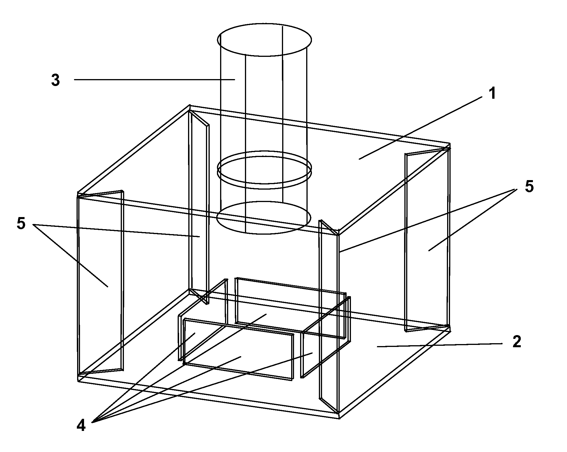
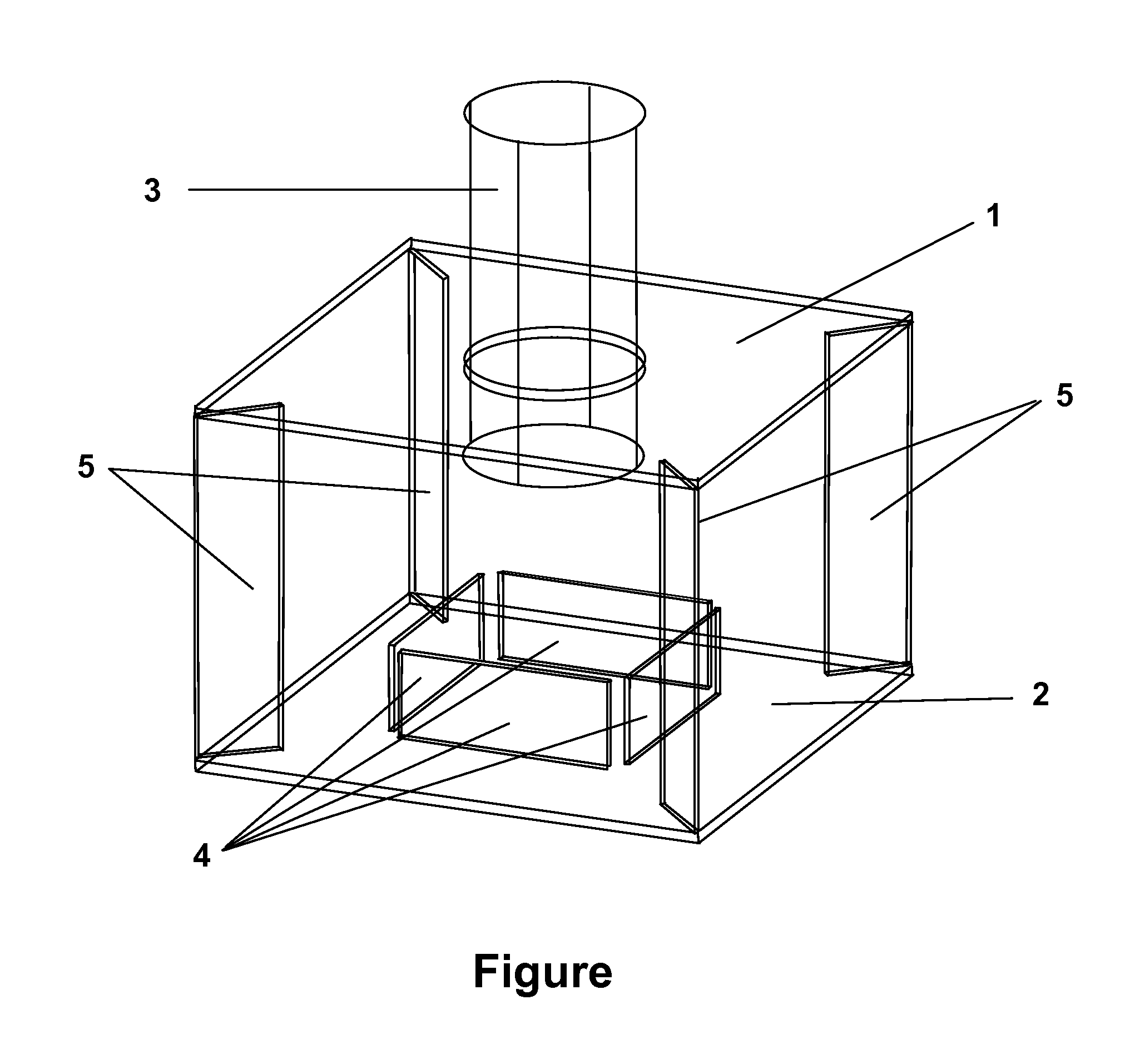
[0033]The FIGURE schematically depicts a prototype embodiment of the invention that has been successfully built and tested. This embodiment comprised two parallel, horizontal plates 1 and 2, with a feed pipe 3 extending vertically and perpendicularly through an opening in upper plate 1. The degree of turbulence was reduced substantially as lower plate 2 changed the flow direction and dissipated the energy of an impinging liquid jet. Baffles 4 further deflected the fluid flow, further dissipating energy. Spacers 5 held plates 1 and 2 in a fixed position relative to one another. Spacers 5 may also, depending on their configuration, secondarily dissipate additional energy from the fluid flow, although these effects are generally minimal because most of the energy has been dissipated before the liquid flow encounters the spacers.
[0034]Alternatively, the feed pipe may be positioned horizontally, parallel to the horizontal plates, for example if available space in a retrofit operation doe...
example 2
[0036]Testing of the prototype embodiment of Example 1, using dye in water, confirmed the non-turbulent dispersal of inflowing liquid into the tank, and in particular has confirmed that turbulence is reduced very substantially as compared to that seen from conventional flow from a simple pipe into a tank, without any turbulence reduction device. Water with dye was pumped through an 8 cm diameter hose at a rate of 23 m3 / h into a tank (volume ˜1 m3) containing water without dye. The test was repeated both with and without the prototype device attached to the end of the hose. Visualization of the resulting flow pattern showed substantial turbulence when the hose was used alone. In sharp contrast, there was almost a complete lack turbulence when the prototype device was attached to the hose. The surface of the water remained calm, despite the discharged of liquid at a rate of 23 m3 / h only ˜40 cm below the surface.
[0037]The novel device practically eliminated the horizontal component of ...
example 3
[0038]The novel device has been successfully implemented and tested in an industrial setting. An existing Graver clarifier in a Louisiana sugar mill was retrofitted with novel turbulence reduction devices in accordance with the present invention. The clarifier had a diameter of 6 m and a height of 7.5 m, including the conical bottom portion. The conventional trays were removed from the Graver clarifier, and overflow collection launders were installed and carefully leveled. Nine turbulence reduction devices, each generally similar to the device of Example 1, were positioned uniformly about 1.5 m above the bottom of the tank. A pre-distributor piping system divided the incoming liquid evenly among the nine turbulence reduction devices. Turbidity of the overflow liquid was measured using a Hach turbidimeter. The retrofit clarifier operated throughout the grinding season, with the exception of some mechanical shutdowns. The retrofit clarifier was one of three clarifiers run in parallel ...
PUM
| Property | Measurement | Unit |
|---|---|---|
| distance | aaaaa | aaaaa |
| length | aaaaa | aaaaa |
| distance | aaaaa | aaaaa |
Abstract
Description
Claims
Application Information
 - R&D
- Intellectual Property
- Life Sciences
- Materials
- Tech Scout
- Unparalleled Data Quality
- Higher Quality Content
- 60% Fewer Hallucinations
Browse by: Latest US Patents, China's latest patents, Technical Efficacy Thesaurus, Application Domain, Technology Topic, Popular Technical Reports.
© 2025 PatSnap. All rights reserved.Legal|Privacy policy|Modern Slavery Act Transparency Statement|Sitemap|About US| Contact US: help@patsnap.com


