
A digital optical fiber remote multi-media transmission user coverage system

A digital optical fiber and digital light technology, applied in optical fiber transmission, transmission system, electromagnetic wave transmission system, etc., can solve the problems of small difference in signal field strength of mobile network, ping-pong effect and pilot frequency pollution, affecting user perception, etc., to achieve indoor Good signal coverage, solving the ping-pong effect and pilot pollution, and overcoming the effect of long construction time

Active Publication Date: 2018-11-02
CHINA YOUKE COMM TECH
View PDF3 Cites 0 Cited by
  • Summary
  • Abstract
  • Description
  • Claims
  • Application Information

AI Technical Summary

Problems solved by technology

[0002] Existing communities, hotels, and guesthouses all have broadband signals, and CAT5 lines or optical fibers are generally used to implement WLAN signals and xPON signals to enter the home to achieve home coverage; while the antennas of traditional indoor distribution systems are all at the door of the house, and the indoor terminal receives The mobile network signal (2G, 3G, 4G) sent by the indoor distribution system passes through multiple walls, and the signal attenuation is serious, resulting in the same field strength between the indoor signal and the mobile network signal from other outdoor macro stations, resulting in ping-pong effect and induced Frequency pollution seriously affects user perception

Method used


Image

  • A digital optical fiber remote multi-media transmission user coverage system
  • A digital optical fiber remote multi-media transmission user coverage system
  • A digital optical fiber remote multi-media transmission user coverage system

Examples


Embodiment Construction

[0023] The technical solution of the present invention will be described in detail below in conjunction with the drawings.

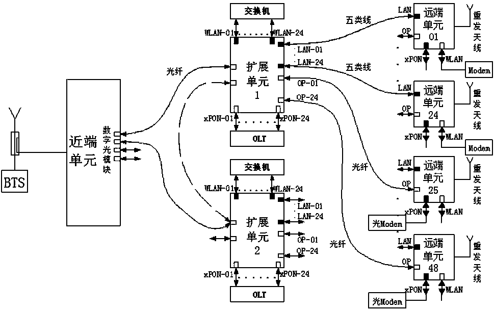
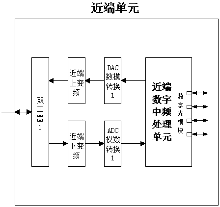
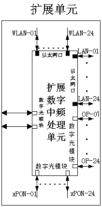
[0024] Such as figure 1 As shown, a digital fiber remote multi-media transmission home coverage system of the present invention includes a near-end unit, an expansion unit, and a remote unit; the near-end unit couples the base station or the remote base station system in the downlink. The mobile network downlink signal enters the near-end down-conversion module through the first duplexer, and converts the mobile network downlink signal into a downlink analog IF signal, and transmits it to the first ADC analog-to-digital conversion module, which is converted into a downlink digital IF signal and then enters the near-end digital IF signal The processing unit is processed by the baseband, the transmission rate is converted, and then the first digital optical module is converted into a downlink digital optical signal to be transmitted to the expansion unit; the ...


PUM


Abstract

The invention relates to a digital optical fiber remote multi-medium transmission household coverage system. The system comprises a near-end unit, an extension unit and a far-end unit. The digital optical fiber remote multi-medium transmission household coverage system has relatively high integration degree through setting of the near-end unit, the extension unit and the far-end unit. Mobile network signals (2G, 3G and 4G) are remotely transmitted to an LAN signal household device (a switch) and an xPON signal household device (an OLT) by digital optical fibers; the mobile network signals, WLAN signals and XPON signals are combined and then are transmitted by original household optical fibers or 0.5 data communication cables. The original data functions of the original household optical fibers and the 0.5 data communication cables are not influenced. Moreover, the household coverage of wireless voices and data is realized. According to the system, the construction difficulty that the traditional indoor distributed system is long in construction time and difficult in property coordination is overcome; the mobile network signals are imported into the house for coverage by the original household optical fibers and 0.5 data communication cables; the difficulty of ping-pong effect and pilot pollution existing in the indoor network signals is solved without rewiring; and the perceptibility of a user is improved.

Description

Technical field [0001] The invention belongs to the technical field of wireless communication equipment, and specifically relates to a digital optical fiber remote multi-media transmission home coverage system. Background technique [0002] Existing communities, hotels, and guesthouses all have broadband signals. Generally, Category 5 lines or optical fibers are used to achieve WLAN signals and xPON signals into the home to achieve home coverage; while the antennas of the traditional indoor distribution system are all at the door of the house, and the indoor terminal receives The mobile network signal (2G, 3G, 4G) sent by the indoor sub-system passes through multiple walls, and the signal attenuation is serious. As a result, the field strength of the indoor signal and the mobile network signal from other outdoor macro stations is not much different, resulting in ping-pong effect and guidance. Frequent pollution seriously affects users’ perception. Summary of the invention [0003...

Claims


Application Information

Patent Timeline
Patent Type & Authority Patents(China)
IPC IPC(8): H04B10/2575
CPCH04B10/25753
Inventor 徐福车范叔亮廖小康
Owner CHINA YOUKE COMM TECH
Learn More