Compressor system and method for operating the compressor system depending on the operating state of a rail vehicle

A technology for compressor systems and rail vehicles, applied to the operating mechanism of railway vehicle brakes, the arrangement of pumps/compressors, components of pumping devices for elastic fluids, etc., which can solve problems such as noise emissions and achieve energy reduction Consumption, lower operating temperature, effect of reduced cooling requirements

Active Publication Date: 2018-04-13
KNORR BREMSE SYST FUR SCHIENENFAHRZEUGE GMBH
View PDF8 Cites 0 Cited by
  • Summary
  • Abstract
  • Description
  • Claims
  • Application Information

AI Technical Summary

Problems solved by technology

Due to the increased air demand of pneumatic suspension systems in stations due to passenger boarding / disembarking, this often leads to switching on compressors and fans during stops at stations and thus to undesired noise emissions

Method used


Image

  • Compressor system and method for operating the compressor system depending on the operating state of a rail vehicle
  • Compressor system and method for operating the compressor system depending on the operating state of a rail vehicle

Examples


Embodiment Construction

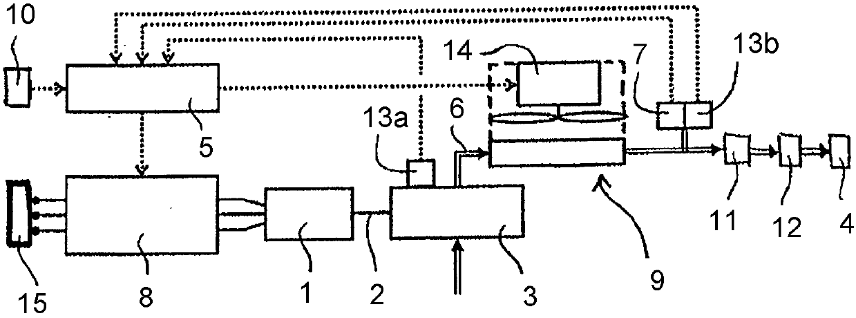
[0023] according to figure 1 , a compressor system for a rail vehicle has an electric motor 1 , which drives a compressor 3 for generating compressed air via a drive shaft 2 . The compressed air produced by the compressor 3 is conveyed via the compressed air duct 6 to the cooling unit 9 with the cooling fan 14 . Downstream of the cooling unit 9 , a pressure sensor 7 and a temperature sensor 13 b are arranged in the compressed air guide line 6 . Furthermore, the compressed air line 6 leads into a pre-separator 11 , after which (downstream) an air treatment unit 12 is connected. The compressed air that has been dried and freed of particles is then fed into the compressed air container 4 . The temperature sensor 13 a arranged on the compressor 3 as well as the temperature sensor 13 b and the pressure sensor 7 all transmit the measured temperature and the measured pressure to the regulating device 5 . In addition, the regulating device 5 also receives signals from the train man...


PUM


Abstract

The invention relates to a compressor system for rail vehicles comprising a compressor (3) driven by an electric motor (1) via a drive shaft (2) for generating at least one compressed air container (4) compressed air, the electric machine (1) can be actuated at least indirectly via a regulating device (5) for operation at at least one rated speed (n) between a maximum speed (m) and a minimum speed (i) The electric machine (1) is furthermore provided with at least one pressure sensor (7) for measuring the pressure for the regulating device (5) in a compressed air supply line (6) arranged downstream of the compressor (3). According to the invention, an actuator (8) for continuously influencing the rotational speed of the electric motor (1) is arranged between the power supply (15) and the electric motor (1), wherein the actuator (8) is implemented by means of the regulating device (5). ) manipulation. In addition, the invention also relates to a method for controlling the compressor system of the invention, wherein the compressor (3) is operated at a variable rotational speed depending on the operating state of the rail vehicle, the rotational speed being at a maximum rotational speed (m) Any intermediate value between the minimum speed (i).

Description

technical field [0001] The invention relates to a compressor system for a rail vehicle comprising a compressor driven by an electric motor via a drive shaft for generating compressed air of at least one compressed air container, wherein the electric motor can at least indirectly Actuated by a regulating device for operating the electric machine at at least one setpoint speed between a maximum and a minimum speed, in addition at least one device for measuring pressure sensor. Furthermore, the invention also relates to a method for controlling the compressor system of the invention. Background technique [0002] Compressors in rail vehicles place many, partly opposing demands, such as high supply performance, sufficient on-duration, low noise emissions, low energy consumption, small installation space and low acquisition costs and Life cycle costs. Here, depending on the operating state of the rail vehicle, the compressor has to meet very different demand profiles. A typic...

Claims


Application Information

Patent Timeline
Patent Type & Authority Patents(China)
IPC IPC(8): F04B35/04F04C28/08F04B41/02F04B49/06F04B49/08F04B49/20F04D25/06F04D27/00
CPCF04B35/04F04B41/02F04B49/06F04B49/08F04B49/20F04B2203/0209F04B2205/05B61D43/00F04D27/0261B60L1/003B60L2200/26B60L2240/36B60L2240/421B60L2260/26B60L2270/142B60T17/02Y02T10/64Y02T30/00Y02B30/70B60T17/002B60T17/06B61H13/34F04B39/0027F04C29/06F04D25/06F04D27/004F04D29/325F04D29/663
Inventor G·阿斯曼T·基普T·默克尔K·黑林R·弗兰克C·米勒
Owner KNORR BREMSE SYST FUR SCHIENENFAHRZEUGE GMBH
Why Eureka
Try Eureka