Supercharge Your Innovation With Domain-Expert AI Agents!

Imprinting device

A technology for placing and transferring bodies, applied in the directions of optics, instruments, opto-mechanical equipment, etc., can solve the problems of bending of the mold 30, deterioration of the transfer of micro-patterns, etc., and achieve the effect of uniform transfer

Active Publication Date: 2016-09-14
PANASONIC INTELLECTUAL PROPERTY MANAGEMENT CO LTD
View PDF5 Cites 4 Cited by
  • Summary
  • Abstract
  • Description
  • Claims
  • Application Information

AI Technical Summary

Problems solved by technology

[0012] However, in the imprint method described in Patent Document 1, there is a problem that when the end portion of the substrate 71 has a step difference, after the pressing roller 10 passes the end portion of the substrate 71, the mold 30 is lifted from the substrate 71, causing the substrate The transfer of minute patterns at the end of 71 deteriorates significantly
For example, if Figure 11 As shown, when the substrate 71 is thicker than the flat plate 40 provided around the substrate 71, the stress of the pressing roller 10 concentrates on the corners of the substrate 71, thereby causing the mold 30 to bend and possibly float from the substrate 71.

Method used


Image

  • Imprinting device
  • Imprinting device
  • Imprinting device

Examples


Embodiment Construction

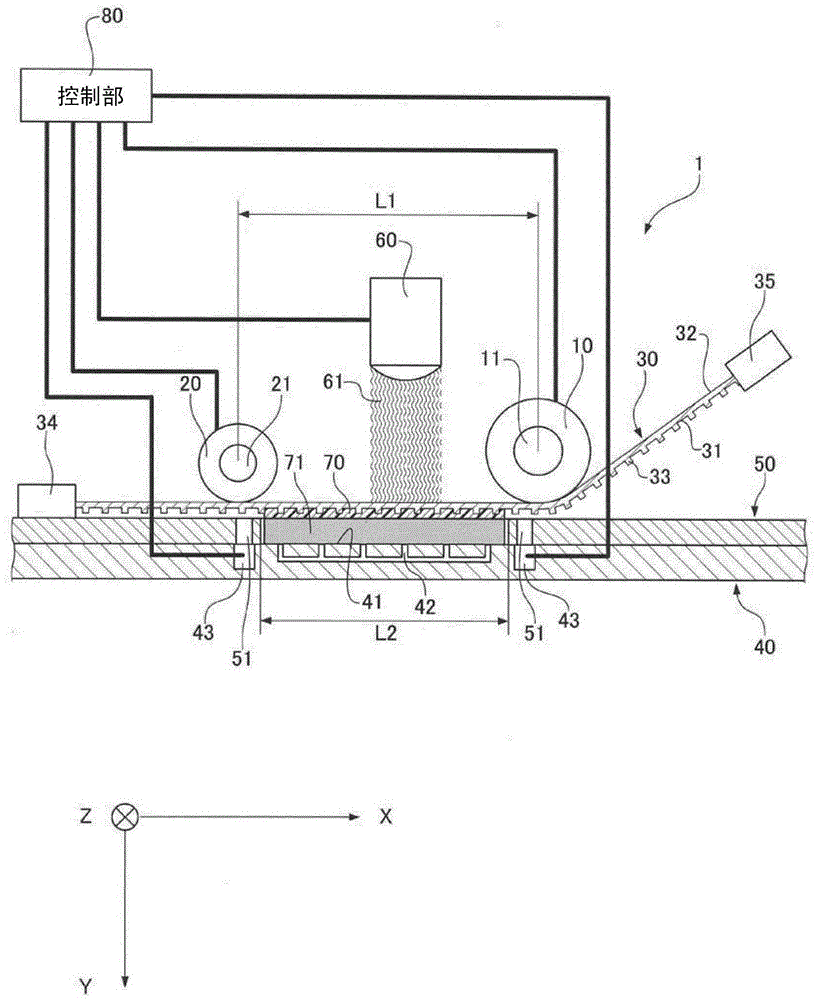
[0043] Hereinafter, the configuration of the imprint apparatus according to the embodiment of the present invention will be described with reference to the drawings. Such as figure 1 As shown, the imprint apparatus 1 according to the embodiment of the present invention includes a pressing roller 10 , a holding roller 20 , a mold 30 , a stage 40 , a flat plate 50 , a UV irradiator 60 , and a control unit 80 . The imprint apparatus 1 according to the embodiment of the present invention employs a roll-type UV imprint method.

[0044] The pressing roller 10 has a cylindrical shape, has a shaft 11 at its center, and is rotatable around the shaft 11 . In addition, the pressing roller 10 is movable on a plane perpendicular to the direction of the shaft 11 (axial direction Z). In other words, the pressing roller 10 is movable in a direction toward the table 40 (pressing direction Y) and a direction perpendicular to the axial direction Z and the pressing direction Y (feeding directi...


PUM


Abstract

An imprinting device (1) capable of realizing uniform transfer regardless of the thickness of a substrate includes a stage (40) having a placement area (41) for placing a substrate (71) to which a transferred object (70) is applied, a thin-plate mold (30) with flexibility having a fine pattern on a first surface (31) facing the placement area (41) of the stage (40), which is held with a predetermined tension and a pressing roll (10) which can press a second surface (32) opposite to the first surface (31) of the mold (30), in which the stage (40) has plural adsorption holes (43) around the placement area (41), and the adsorption holes (43) start adsorption in synchronization with movement of the pressing roll (10).

Description

technical field [0001] The present invention relates to an imprint apparatus for forming minute patterns. Background technique [0002] In recent years, in the optical elements used in products such as displays and lighting, it is desired to realize devices that have discovered new functions that have not been found before. The devices are formed by forming tiny patterns (on the order of nanometers (nm) to the order of micrometers (μm)) that exhibit special optical properties. ) to control the reflection and diffraction of light. As a method of forming a fine pattern as described above, in addition to photolithography and electron beam etching, imprint technology has attracted attention in recent years. The imprint technique refers to a technique of transferring a microscopic pattern of a mold by pressing a mold having a micropattern formed on its surface against a body to be transferred. [0003] Specific methods include thermal imprinting and UV imprinting. The thermal ...

Claims


Application Information

Patent Timeline
IPC IPC(8): B29C59/02
CPCB29C59/02B29C37/0003B29C59/04G03F7/0002B29C2035/0827B29C59/022B29C59/046B29C2059/023B29C59/00B29C59/002B29K2101/12B29K2105/24
Inventor 石川明弘岩濑铁平和田纪彦
Owner PANASONIC INTELLECTUAL PROPERTY MANAGEMENT CO LTD
Features
  • R&D
  • Intellectual Property
  • Life Sciences
  • Materials
  • Tech Scout
  • Unparalleled Data Quality
  • Higher Quality Content
  • 60% Fewer Hallucinations
Learn More