Iron wire heating diversion device

A diversion device and iron wire technology, applied in heat treatment furnaces, heat treatment equipment, furnaces, etc., can solve problems such as uneven heat circulation, incomplete stress removal, and poor heat treatment of iron wires, so as to ensure heat treatment effect and uniformity of heat treatment , Guarantee the effect of thermal effect

Active Publication Date: 2016-09-14
TIANJIN HUAYUAN WIRE PROD
View PDF5 Cites 2 Cited by
  • Summary
  • Abstract
  • Description
  • Claims
  • Application Information

AI Technical Summary

Problems solved by technology

[0002] In the production of steel wire, after the wire rod is drawn to the qualified diameter, the qualified product is wound on the take-up shaft. Since there is stress after the iron wire is drawn, in order to eliminate the stress, it is necessary to use heat treatment to eliminate the stress, which is suitable for production needs. Now The commonly used method of eliminating thermal stress is to feed the iron wire into the heating furnace. The common heating furnace is set with inner and outer layers, the outer layer is the heating layer, and the inner layer is the insulation layer. The disadvantage of the heating furnace is that both heating and insulation are in a static state. , this static heating and heat preservation method is likely to cause uneven heat flow, which in turn leads to poor heat treatment of iron wire and incomplete stress removal

Method used


Image

  • Iron wire heating diversion device
  • Iron wire heating diversion device
  • Iron wire heating diversion device

Examples


Embodiment Construction

[0034] It should be noted that, in the case of no conflict, the embodiments of the present invention and the features in the embodiments can be combined with each other.

[0035] In describing the present invention, it should be understood that the terms "center", "longitudinal", "transverse", "upper", "lower", "front", "rear", "left", "right", The orientations or positional relationships indicated by "vertical", "horizontal", "top", "bottom", "inner", "outer", etc. are based on the orientation or positional relationships shown in the drawings, and are only for the convenience of describing the present invention Creation and simplification of description, rather than indicating or implying that the device or element referred to must have a specific orientation, be constructed and operate in a specific orientation, and therefore should not be construed as limiting the invention. In addition, the terms "first", "second", etc. are used for descriptive purposes only, and should no...


PUM


Abstract

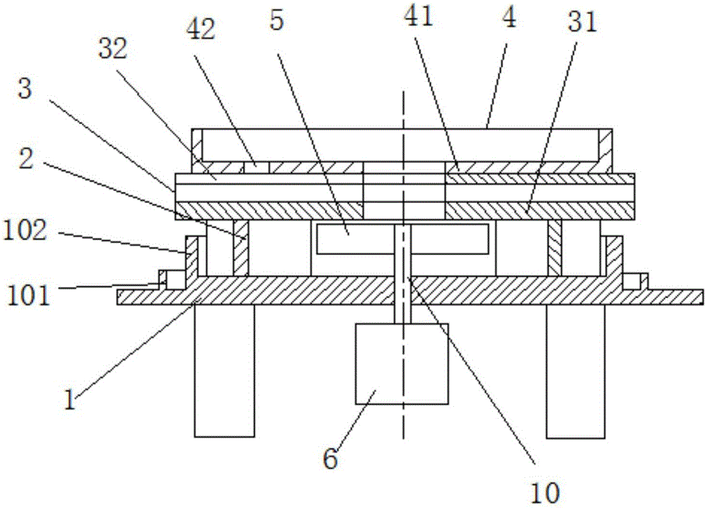
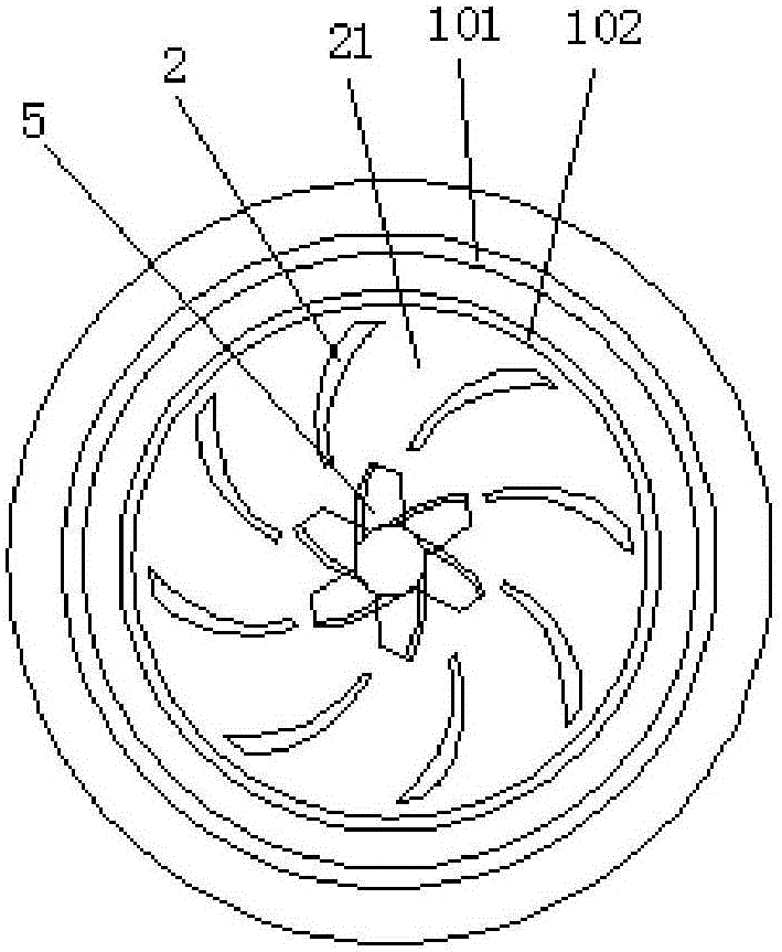
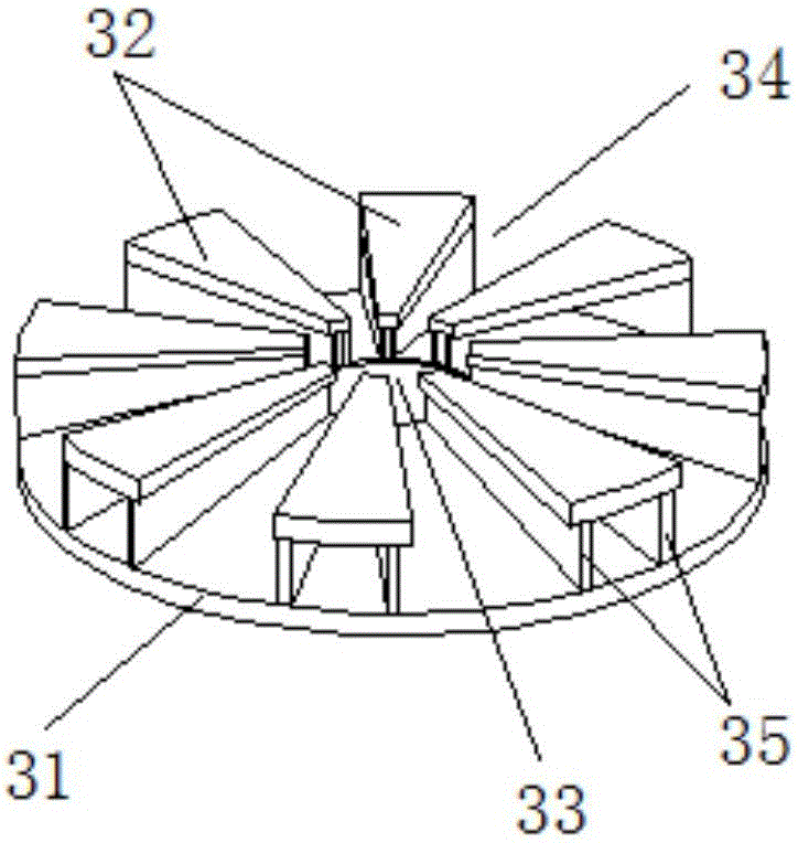
The invention provides an iron wire heating diversion device. The device is arranged in the accommodation cavity of a heating furnace and comprises a support seat, a blower fan, a bracket, and a tray, which are arranged from bottom to top. The blower fan is rotatingly arranged on the support seat through a rotation shaft. The top surface of the support seat is provided with a plurality of baffle plates. The baffle plates are evenly arranged around the blower fan. The center of the bracket is provided with a first air hole. The center of the tray is provided with a second air hole. The bottom surface of the bracket and the top surface of the support seat form a first air channel. Two neighbored baffle plates form a first air channel. In the provided iron wire heating diversion device, the support seat is provided with an air blower and first air channels, the bracket is provided with a first air hole, the tray is provided with a second air hole, the first air hole and the second air hole are opposite to the blower fan; when the blower fan rotates, hot air goes through the second air hole and the first air hole and is discharged from the first air channels, thus thermal energy circulation is formed, the uniformity of temperature in a thermal insulation box can be guaranteed, and the iron wire heating effect is ensured.

Description

technical field [0001] The invention belongs to the field of wire drawing production, and in particular relates to an iron wire heating and guiding device. Background technique [0002] In the production of steel wire, after the wire rod is drawn to the qualified diameter, the qualified product is wound on the take-up shaft. Since there is stress after the iron wire is drawn, in order to eliminate the stress, it is necessary to eliminate the stress by heat treatment, which is suitable for production needs. Now The commonly used method of eliminating thermal stress is to feed the iron wire into the heating furnace. The common heating furnace is set with inner and outer layers, the outer layer is the heating layer, and the inner layer is the insulation layer. The disadvantage of the heating furnace is that both heating and insulation are in a static state. , This static heating and heat preservation method is likely to cause uneven heat flow, which in turn leads to poor heat t...

Claims


Application Information

Patent Timeline
Patent Type & Authority Applications(China)
IPC IPC(8): C21D9/677
CPCC21D9/677
Inventor 宫明江王彦全元斌袁金良
Owner TIANJIN HUAYUAN WIRE PROD
Why Eureka
Try Eureka