Pneumatic sweeping and conveying system of road sweeper

A conveying system and road sweeper technology, which is applied in the field of road sweeper pneumatic cleaning and conveying system, can solve the problems of high fan energy consumption, high use cost, and large dust, and achieve simple structure, improved work efficiency, and reduced pressure loss Effect

Inactive Publication Date: 2016-09-14
杨华
View PDF0 Cites 5 Cited by
  • Summary
  • Abstract
  • Description
  • Claims
  • Application Information

AI Technical Summary

Problems solved by technology

[0002] At present, road sweepers can be basically divided into three types: pure sweeping type, pure suction type and suction sweeping type according to different operating methods; The pure suction road sweeper uses the induced air of the fan to achieve cleaning, and the introduced air is used as a carrier to bring the cleaning objects into the air. The pneumatic conveying channel needs to be equipped with a settling box and a filter to settle and filter the finer particles of garbage and dust, respectively. Dust, the introduced air is filtered and finally discharged from the fan; the pneumatic conveying system of the suction sweeper is similar to that of the pure suction sweeper, the difference is that the cleaning device is also equipped with a sweeping brush, which is composed of the sweeping brush and the pneumatic conveying system Realize cleaning operations; in order to provide sufficient suction for pure suction and suction sweeping road sweepers, the fan equipped with them consumes a lot of energy, is expensive to use, and is not environmentally friendly. Moreover, secondary dust is still generated during operation

Method used


Image

  • Pneumatic sweeping and conveying system of road sweeper
  • Pneumatic sweeping and conveying system of road sweeper
  • Pneumatic sweeping and conveying system of road sweeper

Examples


Embodiment Construction

[0037] The present invention will be described in further detail below in conjunction with the accompanying drawings.

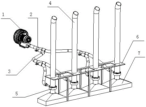
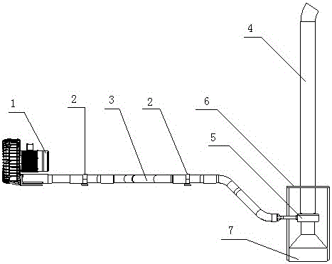
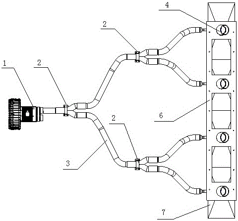
[0038] A road sweeper pneumatic cleaning and conveying system, such as Figure 1 to Figure 5 As shown, it is composed of high-pressure blower 1, air supply passage 3, air amplifier 5, dust suction port 7, delivery pipe 4, dust suction port fixing bracket 6 and air supply pipe fixing sleeve 2; high-pressure blower 1 is connected with air through air supply passage 3 The amplifier 5 is connected, the air amplifier 5 is connected above the dust suction port 7, the delivery pipe 4 is arranged above the air amplifier 5, the dust suction port 7 is fixed by the dust suction port fixing bracket 6, and the air supply pipe is fixed by the air supply pipe fixed sleeve 2; The air supply passage 3 is provided with at least two branches; the air supply passage 3 branches are provided with multiple in order to improve the sweeping width of the road sweeper, and the number o...


PUM


Abstract

A pneumatic sweeping and conveying system of a road sweeper is composed of a high-pressure air blower, an air supply passage, an air amplifier, a dust suction opening, a conveying pipe, a dust suction opening fixing support and an air supply pipe fixing sleeve. The high-pressure air blower is connected with the air amplifier through the air supply passage. The air amplifier is connected to the position above the dust suction opening. The conveying pipe is arranged above the air amplifier. The dust suction opening is fixed through the dust suction opening fixing support. The air supply pipe is fixed through the air supply pipe fixing sleeve. The air supply passage is provided with at least two branches. The air supply passage is formed by a straight air supply pipe a, a straight air supply pipe b, a straight connecting pipe, a cavel-shaped tee joint, a reversing air supply pipe a, a reversing air supply pipe b, a reducing pipe and a straight joint. The pneumatic sweeping and conveying system has the advantages that air entering a draught fan is natural air and does not need to be filtered, therefore, the pneumatic sweeping and conveying system is simplified, pressure losses are reduced, and the work efficiency of the draught fan is improved; the pneumatic sweeping and conveying system is simple in structure, low in pressure loss and energy consumption and environmentally friendly, and saving energy.

Description

technical field [0001] The invention relates to the field of road cleaning equipment, in particular to a road sweeper pneumatic cleaning and conveying system. Background technique [0002] At present, road sweepers can be basically divided into three types: pure sweeping type, pure suction type and suction sweeping type according to different operating methods; The pure suction road sweeper uses the induced air of the fan to achieve cleaning, and the introduced air is used as a carrier to bring the cleaning objects into the air. The pneumatic conveying channel needs to be equipped with a settling box and a filter to settle and filter the finer particles of garbage and dust, respectively. Dust, the introduced air is filtered and finally discharged from the fan; the pneumatic conveying system of the suction sweeper is similar to that of the pure suction sweeper, the difference is that the cleaning device is also equipped with a sweeping brush, which is composed of the sweeping...

Claims


Application Information

Patent Timeline
Patent Type & Authority Applications(China)
IPC IPC(8): E01H1/08
CPCE01H1/0863
Inventor 杨华
Owner 杨华
Why Eureka
Try Eureka