
Electro-optical phase modulation system

An electro-optic phase modulation, electro-optic crystal technology, applied in optics, nonlinear optics, instruments, etc., can solve problems such as affecting the accuracy of phase modulation, influence, and poor phase modulation accuracy.

Inactive Publication Date: 2016-09-14
NAT TIME SERVICE CENT CHINESE ACAD OF SCI
View PDF4 Cites 0 Cited by
  • Summary
  • Abstract
  • Description
  • Claims
  • Application Information

AI Technical Summary

Problems solved by technology

In the above method, when the light beam reaches the light exit surface (parallel to the light incident surface), the light exit surface will reflect the light beam and reflect the light beam to the light incident surface, and the light incident surface will reflect the received reflected light beam again, The light beam inside the electro-optic crystal is reflected back and forth between the light incident surface and the light exit surface, thereby causing residual amplitude modulation, which has a bad influence on the accuracy of phase modulation, and the higher the residual amplitude modulation is, the more accurate the phase modulation is. The greater the influence of degree
[0004] In the prior art, in order to reduce the residual amplitude modulation, the light incident surface and the light exit surface of the electro-optic crystal are generally coated with a light-transmitting film, and the light beam is reduced back and forth between the light incident surface and the light exit surface through the light-transmitting film. However, through The light-transmitting film cannot completely prevent the light beam from being reflected back and forth between the light incident surface and the light exit surface, so that there is still a back and forth reflected light beam between the light incident surface and the light exit surface, which will cause residual amplitude modulation and affect the accuracy of phase modulation

Method used


Image

  • Electro-optical phase modulation system
  • Electro-optical phase modulation system
  • Electro-optical phase modulation system

Examples


Embodiment Construction

[0017] In order to make the purpose, technical solutions and advantages of the embodiments of the present invention clearer, the technical solutions in the embodiments of the present invention will be clearly and completely described below in conjunction with the drawings in the embodiments of the present invention. Obviously, the described embodiments It is a part of embodiments of the present invention, but not all embodiments. Based on the embodiments of the present invention, all other embodiments obtained by persons of ordinary skill in the art without making creative efforts belong to the protection scope of the present invention.

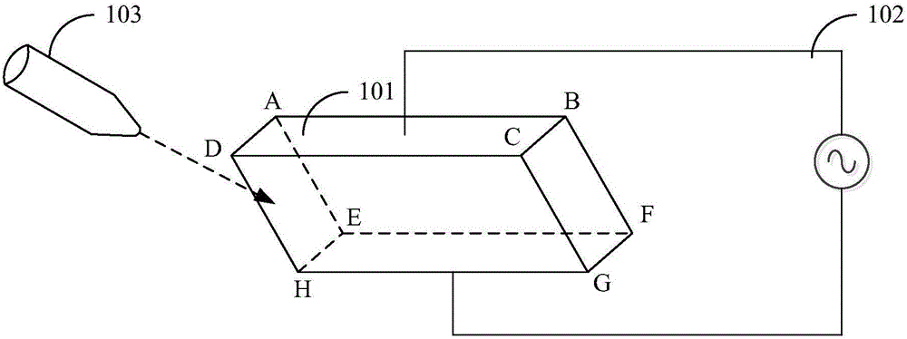
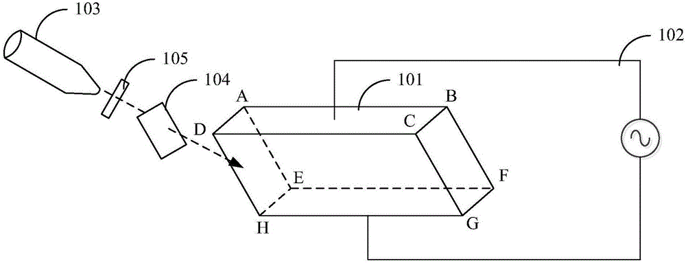
[0018] The electro-optic phase modulation system involved in the embodiment of the present invention is applied to transverse electro-optic phase modulation, and the electro-optic phase modulation system can modulate the phase of the light beam. During the phase modulation process, the accuracy of the phase modulation is affected due to the l...


PUM


Abstract

The embodiment of the invention provides an electro-optical phase modulation system which comprises an electro-optical crystal, a radio-frequency circuit and a light source, wherein a light incident surface and a light emitting surface of the electro-optical crystal are parallel, an upper electrode surface and a lower electrode surface of the electro-optical crystal are parallel, the light incident surface and the light emitting surface are arranged between the upper electrode surface and the lower electrode surface, and the included angle between the light incident surface and the upper electrode surface is a Brewster angle; two electrodes of the radio-frequency circuit are respectively connected with the upper electrode surface and the lower electrode surface and are used for transmitting radio-frequency signals to the upper electrode surface and the lower electrode surface so as to form an electric field vertical to the upper electrode surface between the upper elelctrode surface and the lower electrode surface; and a light source is arranged at one side of the light incident surface, and the included angle between the light beams generated by the light source and the light incident surface is a Brewster angle. The electro-optical phase modulation system is used for reducing residual amplitude modulation and further improving the precision of phase modulation.

Description

technical field [0001] Embodiments of the present invention relate to the technical field of laser control, and in particular to an electro-optic phase modulation system. Background technique [0002] Due to the high sensitivity of electro-optic phase modulation technology, electro-optic phase modulation technology is widely used in atomic spectroscopy, ultra-stable laser and other technical fields. At present, electro-optic phase modulation is generally realized by electro-optic phase modulator. for electro-optic crystals. [0003] At present, electro-optic phase modulation is divided into transverse electro-optic phase modulation and longitudinal electro-optic phase modulation. In transverse electro-optic modulation, it is necessary to ensure that the direction of the electric field is perpendicular to the direction of the beam inside the electro-optic crystal. The upper surface and the lower surface of the crystal send radio frequency signals, so that an electric field w...

Claims


Application Information

Patent Timeline
IPC IPC(8): G02F1/03
CPCG02F1/0311G02F1/0316G02F2203/50G02F1/0327G02F1/0344G02F2202/20G02F2203/07
Inventor 姜海峰邰朝阳张颜艳张龙闫露露赵文宇张首刚
Owner NAT TIME SERVICE CENT CHINESE ACAD OF SCI
Learn More