Device for forming linear double eyelids

A shaper and bodyweight technology, applied in ophthalmic surgery, etc., can solve problems such as difficulty in controlling double eyelid line symmetry, inability to produce reliable adhesion, and lack of static positioning, so as to solve eyeball damage, shorten operation time, and reduce bleeding Effect

Inactive Publication Date: 2016-09-21
刘生
View PDF8 Cites 1 Cited by
  • Summary
  • Abstract
  • Description
  • Claims
  • Application Information

AI Technical Summary

Problems solved by technology

[0002] The existing thread double eyelid surgery, one is to operate without eye protection equipment, the main problem is that it may cause damage to the eyeball, once the damage is mostly irreversible, it may cause blindness to the recipient
The second is to operate under the condition of eyeball protectors, but the existing eyeball protectors are thicker and larger
[0003] The above two methods cannot solve the problem that when the orbital septal fat sags below the double eyelid line, because there is orbital septal fat between the orbicularis oculi and the levator fascia, no reliable adhesion can be produced, resulting in the disappearance of the double eyelid
Moreover, for double eyelid surgery that requires eyelash lift at the same time, the above two methods only rely on the operator's dynamic lifting to complete, without accurate static positioning, it is difficult to control the symmetry of the double eyelid line

Method used


Image

  • Device for forming linear double eyelids
  • Device for forming linear double eyelids

Examples


Embodiment Construction

[0018] The present invention will be further described below in conjunction with the accompanying drawings.

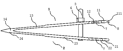
[0019] like figure 1 As shown, the present invention includes an upper clip 1 and a lower clip 2 with similar shapes, and the upper clip 1 includes an upper clip head 11, an upper clip neck 12, and an upper clip body 13 connected in sequence. , The upper clip tail 14, the lower clip 2 includes the lower clip head 21, the lower clip neck 22, the lower clip body 23, and the lower clip tail 24 connected in sequence. The upper clip 1 and the lower clip 2 are matched and connected together at the tail 14 of the upper clip and the tail 24 of the lower clip, and gradually become thinner towards the end. , can make the upper clip 1 and the lower clip 2 normally open.

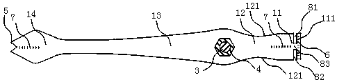
[0020] The lower surface of the upper clip head 11 is provided with a row needle groove 8 , and a leading edge 111 is provided at the end. combine figure 2 As shown, the row needle slot 8 includes a needle ...


PUM


Abstract

The invention discloses a device for forming linear double eyelids. The device solves the problems that an existing device is likely to damage the eyeballs, inaccurate in positioning and unreliable in adhesion. The device is characterized by comprising an upper clamping piece and a lower clamping piece, wherein the shape of the upper clamping piece is similar to that of the lower clamping piece; the tail of the upper clamping piece and the tail of the lower clamping piece are connected together, a two-point double eyelid positioner is arranged at the tail ends, and a bolt penetrates through the top end of an upper clamping piece body and the top end of a lower clamping piece body and is sleeved with a nut; a needle moving groove is formed in the lower surface of an upper clamping piece head, a front edge is arranged at the tail end of the upper clamping piece head, the needle moving groove comprises a needle inlet and a needle outlet, and the two side faces of an upper clamping piece neck and the two side faces of a lower clamping piece neck are Bessel curved surfaces in smooch transition. The device is simple in structure and integrates protecting, designing, positioning and fixing; it is guaranteed that double eyelids are not influenced while the lower clamping piece protects the eyeballs absolutely reliably, the upper clamping piece and the lower clamping piece perform clamping to accurately fix the positions of double eyelid lines, it is guaranteed that no displacement is generated in an operation, pendulous orbital phrenic fat moves upwards, the orbicularis oculi muscle is compressed at the same time, and reliable adhesion is guaranteed.

Description

technical field [0001] The invention relates to an instrument for cosmetic plastic surgery, more specifically a thread double eyelid instrument. Background technique [0002] The existing thread double eyelid surgery, one is to operate under the situation of no eyeball protection device, its main problem is that it may cause damage to the eyeball, once the damage is mostly irreversible damage, it may cause blindness to the recipient. The 2nd, operate under the condition that eyeball protector is arranged, but existing eyeball protector is all thicker. Although the eyeball was protected, the foreign body sensation in the eye of the recipient was very obvious, extremely painful and had a strong sense of fear, and the shape and position of the double eyelid design line were destroyed. [0003] The above two methods cannot solve the problem that when the orbital septal fat sags below the double eyelid line, because there is orbital septal fat between the orbicularis oculi and t...

Claims


Application Information

Patent Timeline
Patent Type & Authority Applications(China)
IPC IPC(8): A61F9/007
CPCA61F9/007
Inventor 刘生
Owner 刘生
Why Eureka
Try Eureka