A main clamping head of a vertical broaching machine

A vertical broaching machine and tool clamping technology, which is applied in the direction of manufacturing tools, chucks, metal processing machinery parts, etc., can solve problems such as unsmooth clamping tools, accumulation of iron filings, scratches on jaws, etc., to avoid clamping failure Stable, reduce the accumulation of iron filings, good clamping effect

Active Publication Date: 2019-07-12
CHANGSHA SISHENG INTELLIGENT EQUIP
View PDF6 Cites 0 Cited by
  • Summary
  • Abstract
  • Description
  • Claims
  • Application Information

AI Technical Summary

Problems solved by technology

[0002] At present, most of the main clamping heads used on vertical broaching machines are as attached figure 1 As shown in the semicircle, when the broach leaves the chuck, the iron filings enter the gap between the chuck body and the jaw a, and it is difficult to discharge the iron filings even if a device with air blowing or flushing is used , when the sliding table squeezes the jaws upward, the jaws are blocked and the broach cannot be clamped, and the broaching cycle cannot run
The section structure is attached figure 2 As shown in the mushroom-shaped main clamping head, although no iron filings will be retained between the claw a' on the main clamping head and the chuck body, the claw a' is easy to bear due to the bearing when the broach is blocked. Severe deformation due to broaching force, especially for large-tonnage broaching machines
The main clamping head of the above-mentioned vertical broaching machine has the following disadvantages: the force is not good, iron filings are accumulated, the tool clamping is not smooth during the operation of the machine tool, and the jaws are often scratched by iron filings and need to be replaced, making the parts processed by the broaching machine The efficiency of the product is low, and the cost of replacing parts is high
The positioning pin in the chuck body structure is mainly used to clamp the handle of the broach, prevent the broach from sliding down, and facilitate the discharge of iron filings generated during the operation of the broach, and cannot solve the problem of the gap between the clamping tool body and the jaws. The problem of accumulating iron filings

Method used


Image

  • A main clamping head of a vertical broaching machine
  • A main clamping head of a vertical broaching machine
  • A main clamping head of a vertical broaching machine

Examples


Embodiment Construction

[0024] The present invention will be further described below in conjunction with the accompanying drawings and embodiments.

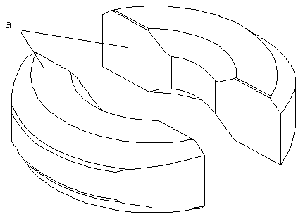
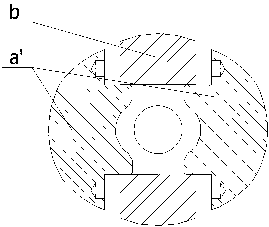
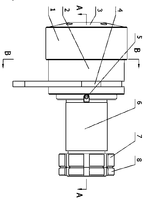
[0025] refer to Figure 3~6 , a main clamping head of a vertical broaching machine, comprising a top cap 3, a sleeve 1, a sliding sleeve 2, a claw 9, a clamping body 6 and a shift fork 4; the top cap 3 is fixed on one side of the clamping body 6 One end of the claw 9 is connected with the sliding sleeve 2; one end of the sliding sleeve 2 is connected with the top cap 3 through the sleeve 1, and the other end is connected with the shift fork 4, and slides up and down driven by the shift fork 4; The inner side of the sliding sleeve 2 is provided with several claws 9, which are distributed on the outer side of the cutter body 6 in a circular manner. The claw 9 is a cylindrical pin structure;

[0026] The claw 9 includes an integrally formed pin 93 and a pin cap 91, the front end of the pin 93 is provided with an arc 94 inclined to the center point of the...


PUM


Abstract

A main tool chuck of a vertical broaching machine comprises a pressing cap, a cover, a sliding sleeve, clamping jaws, a tool clamping body and a shifting fork, wherein the pressing cap is fixed above the tool clamping body; one ends of the clamping jaws are connected with the sliding sleeve; one end of the sliding sleeve is connected with the pressing cap through the cover, the other end of the sliding sleeve is connected with the shifting fork, and the sliding sleeve is driven by the shifting fork to slide up and down; and the plurality of clamping jaws are arranged on the inner side of the sliding sleeve, and the clamping jaws are of cylindrical pin structures. According to the main tool chuck of the vertical broaching machine, through changing the structures of the clamping jaws and adopting the cylindrical pin structures, the accumulation of iron scraps on the main tool chuck in the use process of the vertical broaching machine is reduced, and accordingly, the phenomenon that the clamping of a broaching tool by the clamping jaws is unstable is avoided.

Description

technical field [0001] The invention relates to a vertical broaching machine, in particular to a main clamping cutter head of the vertical broaching machine. Background technique [0002] At present, most of the main clamping heads used on vertical broaching machines are as attached figure 1 As shown in the semicircle, when the broach leaves the chuck, the iron filings enter the gap between the chuck body and the jaw a, and it is difficult to discharge the iron filings even if a device with air blowing or flushing is used , when the sliding table squeezes the jaws upward, the jaws are blocked and the broach cannot be clamped, and the broaching cycle cannot run. The section structure is attached figure 2 As shown in the mushroom-shaped main clamping head, although no iron filings will be retained between the claw a' on the main clamping head and the chuck body, the claw a' is easy to bear due to the bearing when the broach is blocked. Severe deformation due to broaching f...

Claims


Application Information

Patent Timeline
Patent Type & Authority Patents(China)
IPC IPC(8): B23B31/10B23B31/16B23Q11/00
CPCB23B31/102B23B31/16287B23B2270/28B23Q11/005
Inventor 赵建华陈留洋李敢刘代波
Owner CHANGSHA SISHENG INTELLIGENT EQUIP
Why Eureka
Try Eureka