Welding positioning clamp

A welding positioning and fixture technology, used in welding equipment, auxiliary welding equipment, welding/cutting auxiliary equipment, etc. The device has the advantages of simple structure and improved work efficiency

Active Publication Date: 2016-09-21
GUANGZHOU YUANSHENG AUTOMATION TECH CO LTD
View PDF4 Cites 5 Cited by
  • Summary
  • Abstract
  • Description
  • Claims
  • Application Information

AI Technical Summary

Problems solved by technology

[0002] Fixtures are important process equipment in the machinery manufacturing industry. During the machining process, some workpieces need to be welded, especially when welding some large steel structure workpieces. Due to the size requirements of the welded workpieces and the thickness of the steel plate, etc. The problem makes it difficult to operate when the workpiece is fixed and positioned, which can easily lead to errors such as welding misalignment, resulting in waste of materials, reducing work efficiency and increasing production costs
[0003] In the prior art, some fixtures are used to position and fix the workpiece to be processed, and then weld it. However, it is difficult for the fixtures in the prior art to ensure the accuracy of the axial and radial directions of the workpiece. Tools such as squares are used for positioning and then welding. For large workpieces, this method is not accurate enough for positioning. In addition, large workpieces are bulky and have irregular frames. Different fixtures need to be selected for fixing, which is costly. It is more difficult to reach the workpiece that needs to be turned over for welding, which affects the processing efficiency

Method used


Image

  • Welding positioning clamp
  • Welding positioning clamp
  • Welding positioning clamp

Examples


Embodiment Construction

[0022] The present invention will be described in detail below in conjunction with the accompanying drawings.

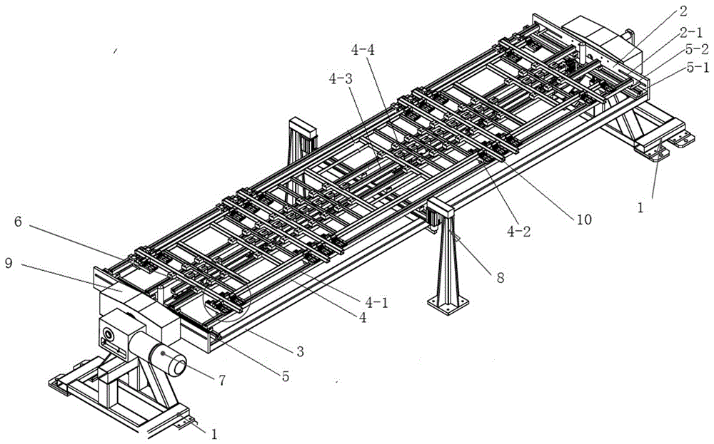
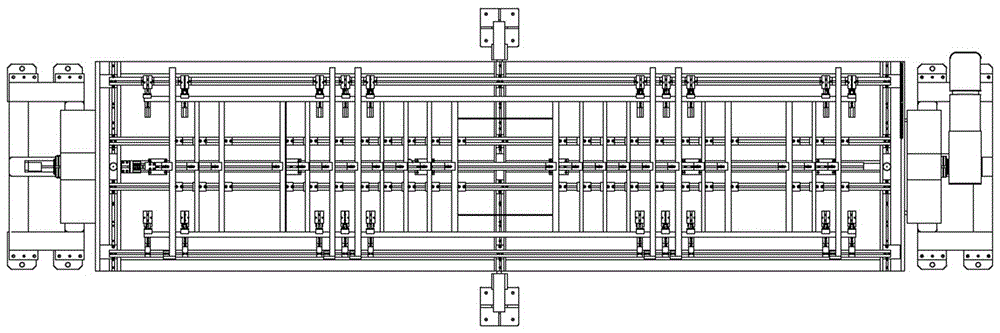
[0023] like Figure 1~Figure 3 As shown, the present invention provides a welding positioning fixture, including a pair of first support frames 1 fixedly arranged on the ground, and a fixed clamp body arranged between the first support frames 1;

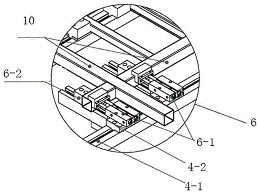
[0024] The first support frame 1 is a trapezoidal structure, the bottom end of the first support frame 1 is fixedly installed on the ground by bolts, and a motor 7 for driving the fixed clamp body to rotate is installed on the upper end of the first support frame 1, and the output of the motor 7 The shaft is connected with the baffle plate 2 through the connector 9. When the motor 7 is working, the output shaft drives the baffle plate to rotate, and then drives the longitudinal guide groove 4, the pressing device 6 and the workpiece 10 to rotate.

[0025] Further, the fixing clip specifically includes: a baffle 2 installed...


PUM


Abstract

The invention discloses a welding positioning clamp, and relates to the technical field of welding tools. The welding positioning clamp comprises a pair of first supporting frames which are fixedly arranged on the ground, and a fixing clamp body which is arranged between the first supporting frames. The first supporting frames are provided with motors used for driving the fixing clamp body to rotate. The fixing clamp body comprises baffles installed on the first supporting frames. A base is installed between the baffles, and the base is provided with a plurality of longitudinal guide grooves capable of sliding. A plurality of pressing devices used for clamping workpieces are installed in the longitudinal guide grooves. The welding positioning clamp can move flexibly according to the size and structure of each workpiece, so that fixing and clamping work of each workpiece is completed. In addition, due to the fact that the supporting frames of the clamp are provided with the rotating motors, the fixing clamp body can be driven to turn over so that multi-angle welding can be achieved. The welding positioning clamp is simple in structure, flexible in fixation, high in applicability, and capable of improving work efficiency and lowering the defective rate in actual welding.

Description

technical field [0001] The invention relates to the technical field of welding tools, in particular to a welding positioning fixture. Background technique [0002] Fixtures are important process equipment in the machinery manufacturing industry. During the machining process, some workpieces need to be welded, especially when welding some large steel structure workpieces. Due to the size requirements of the welded workpieces and the thickness of the steel plate, etc. The problem makes it difficult to operate when the workpiece is fixed and positioned, which easily leads to errors such as welding misalignment, resulting in waste of materials, reducing work efficiency, and increasing production costs. [0003] In the prior art, some fixtures are used to position and fix the workpiece to be processed, and then weld it. However, it is difficult for the fixtures in the prior art to ensure the accuracy of the axial and radial directions of the workpiece. Square and other tools are...

Claims


Application Information

Patent Timeline
Patent Type & Authority Applications(China)
IPC IPC(8): B23K37/04
CPCB23K37/0443
Inventor 曾加亮邓辉
Owner GUANGZHOU YUANSHENG AUTOMATION TECH CO LTD
Why Eureka
Try Eureka