Upper injection molding mold

A technology for injection molding and shoe uppers, which is applied to footwear, home appliances, and other home appliances. It can solve problems such as unsatisfactory requirements, increased mold manufacturing costs, and limited shoe aesthetics, so as to achieve rich variety and expand Consumer groups, the effect of enriching appearance

Inactive Publication Date: 2016-09-21
李建华
View PDF5 Cites 6 Cited by
  • Summary
  • Abstract
  • Description
  • Claims
  • Application Information

AI Technical Summary

Problems solved by technology

And the appearance of shoes is determined by the outer layer of the shoe. The existing shoe forming mold can only inject the outer layer of the shoe. It will increase the production cost of the mold, and on the other hand, the modeling method is single, and the aesthetics of the obtained shoes will be limited.
In addition, the outer layer of the shoe must take into account the requirements of aesthetics, firm bonding, and anti-aging requirements. These requirements are superimposed on the same material, and the characteristics of the same material are unlikely to meet these requirements at the same time. , that is, the requirements of all aspects of this shoe can not be well met

Method used


Image

  • Upper injection molding mold
  • Upper injection molding mold
  • Upper injection molding mold

Examples


Embodiment Construction

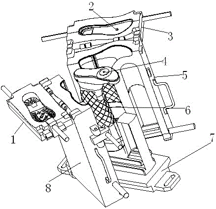
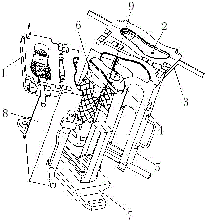
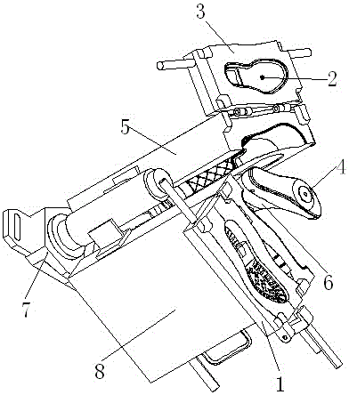
[0024]As shown in the figure, the shoe upper injection molding mold is mainly carried out through the forming mold, and some actions on the forming mold are mainly carried out manually, including the base 7, the left movable mold 8 and the right movable mold 5 are hinged at one end of the base 7 On the side, an inner last 6 is fixed at the middle position of the base 7 . The surfaces facing each other of the left movable mold 8 and the right movable mold 5 are symmetrically provided with mold cavities, and the mold cavities wrap the inner last 6 after mold closing. The free ends of the left movable mold 8 and the right movable mold 5 are provided with fastening structures. After closing the molds, the fastening structure is operated to fasten the left movable mold 8 and the right movable mold 5 together.

[0025] Forming mold also can not comprise base 7, and left movable mold 8 and right movable mold 5 are respectively directly fixed on the power mechanism on the automatic sh...


PUM


Abstract

The invention discloses an upper injection molding mold. The problems that an existing upper mold can only mold double-layer injection molded uppers, a new injection molded layer can only be formed outside the former layer, and consequently the quality of injection molded shoes cannot be guaranteed are solved. The upper injection molding mold structurally comprises a left movable mold body, a right movable mold body and an inner shoe last. The left movable mold body or the right movable mold body is provided with an injection molding opening. The upper injection molding mold is characterized in that the molding mold is used for injecting a middle shoe layer on the inner surface of an outer shoe layer forming an upper; an injection molding structure is arranged on the outer end face of the inner shoe last and is located on the inner side of the outer shoe layer when the inner shoe last is sleeved with the outer shoe layer, so that a through hole is formed in the position, on the injection molding structure, of the outer shoe layer conveniently; the injection molding opening is matched with the injection molding structure after mold assembling; and the inner end side of the surface of a cavity of the left movable mold body and the inner end side of the surface of a cavity of the right movable mold body are provided with limiting structures, and the limiting structure of the left movable mold body and the limiting structure of the right movable mold body form a closed annular structure after mold assembling.

Description

technical field [0001] The invention relates to a mold for making shoes, in particular to a mold which can be used for injection molding of at least two layers of shoe uppers. Background technique [0002] Usually, the existing injection molded shoes generally have a two-layer structure, that is, an inner layer of a shoe and an outer layer of a shoe, and the inner layer of a shoe is generally made of cloth as an insulating layer. This type of shoe is prepared and molded by a forming mold. The structure of the existing forming mold includes a base, a left movable mold and a right movable mold are hinged on one end of the base, and an inner last is fixed at the middle of the base. The upper end of the last is molded into a human foot-like foot. When making the preparation, first put the inner layer of the shoe on the inner last, close the left movable mold and the right movable mold, use the injection molding machine to inject materials into the mold cavity, and form a shoe u...

Claims


Application Information

Patent Timeline
Patent Type & Authority Applications(China)
IPC IPC(8): B29D35/08B29D35/14
CPCB29D35/0018B29D35/061B29D35/081B29D35/126B29D35/146
Inventor 李建华
Owner 李建华
Why Eureka
Try Eureka