Al technical title is built by PatSnap Al team. It summarizes the technical point description of the patent document.
A paper plate and paper edge technology, applied in the field of utensil production, can solve the problems of rare rectangles, etc., and achieve the effect of ingenious conception, beautiful shape and strong practicability
Inactive Publication Date: 2016-09-21
李平
View PDF0 Cites 0 Cited by
Summary
Abstract
Description
Claims
Application Information
AI Technical Summary
This helps you quickly interpret patents by identifying the three key elements:
Problems solved by technology
Method used
Benefits of technology
Problems solved by technology
[0002] At present, most of the known paper trays are square, and rectangular ones are rare
Method used
Image
Click on the blue label to locate the original text in one second.
Reading with bidirectional positioning of images and text.
Examples
Embodiment Construction
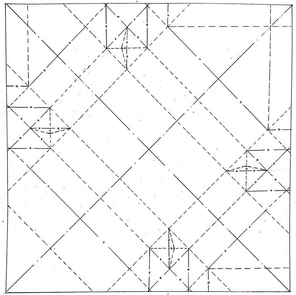
[0027] A dotted line is used to indicate the positive fold line of the front half fold, that is, when folding, the front and the front of the paper are folded relative to each other; a solid line plus a circle indicates the reverse fold line of the reverse face fold, that is, when the paper is folded, the back and the back of the paper are folded opposite each other; the solid line plus a dot indicates the indicator line ;
[0028] Take a square paper and make a diagonal indicator line. The diagonal line with high left and low right is the high left diagonal indicator line, and the diagonal line with low left and high right is the low left diagonal indicator line. Two diagonal lines The indicator lines intersect at the center point of the square paper;
[0029] On the left high diagonal line, make three folding lines perpendicular to the left high diagonal line on both sides of the center point of the square paper, from the two ends of the left high diagonal line to the square...
PUM
Abstract
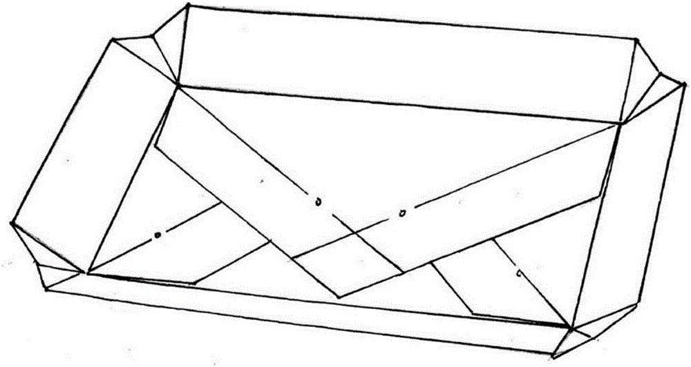
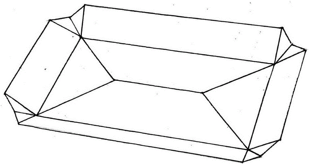
The invention provides a long paper tray, and relates to a method for manufacturing paper utensils. The method includes the steps that a piece of square paper is obtained, and a low left positive folded line, a first-second intersection negative folded line, a third-sixth intersection positive folded line, a fifth-sixth intersection negative folded line, a fourth-fifth intersection positive folded line, a line one negative folded line, a line one positive folded line, a line two positive folded line, a line two negative folded line, a tray bottom positive folded line, a tray height positive folded line, a line four negative folded line, a line four positive folded line, a line five positive folded line, a line five negative folded line, a third-fourth intersection perpendicular line negative folded line and other folded lines are made; the square paper is folded into an initial shape of the long paper tray according to the folded lines; the paper is folded and attached according to a superposition seventh intersection negative folded line and a superposition eighth intersection negative folded line; and the lower left large corner is located at the bottommost layer, the upper left large corner and the lower right large corner are located above the lower left large corner, the upper right large corner is located at the uppermost portion, and the paper corner portion of the upper right large corner is inserted below the lower left large corner, and accordingly the long paper tray is formed. The long paper tray is ingenious in conception, novel in design, easy to fold and attractive in appearance. The defect that when multiple paper corners are folded at one position, engaging cannot be achieved and upwarp is likely to happen is overcome. The structure is firm and practicability is high.
Description
technical field [0001] The invention relates to a method for making a vessel, in particular to a method for making a paper vessel. Background technique [0002] At present, known paper trays are in the majority with square ones, and rectangular ones are relatively rare. Contents of the invention [0003] In order to overcome the disadvantage that most of the existing paper trays are square and the rectangular ones are relatively rare, the present invention provides a method for making long paper trays. [0004] The technical solution adopted by the present invention to solve its technical problem is: take square paper, make diagonal indicator line, the diagonal line with high left and low right is the high diagonal indicator line on the left, and the diagonal line with low left and high right is The left lower diagonal indicator line, the two diagonal indicator lines intersect at the center point of the square paper; [0005] On the left high diagonal line, make three fo...
Claims
Application Information
Patent Timeline
Application Date:The date an application was filed.
Publication Date:The date a patent or application was officially published.
First Publication Date:The earliest publication date of a patent with the same application number.
Issue Date:Publication date of the patent grant document.
PCT Entry Date:The Entry date of PCT National Phase.
Estimated Expiry Date:The statutory expiry date of a patent right according to the Patent Law, and it is the longest term of protection that the patent right can achieve without the termination of the patent right due to other reasons(Term extension factor has been taken into account ).
Invalid Date:Actual expiry date is based on effective date or publication date of legal transaction data of invalid patent.
