An emergency unlocking device for a door system
What is Al technical title?
Al technical title is built by PatSnap Al team. It summarizes the technical point description of the patent document.
An emergency unlocking and door system technology, applied in the field of emergency unlocking devices, can solve the problems of inability to realize remote control unlocking, difficult maintenance, and high cost, and achieve the effects of good application prospects, convenient assembly and simple structure.
Active Publication Date: 2017-12-12
NANJING KANGNI MECHANICAL & ELECTRICAL
View PDF4 Cites 0 Cited by
Summary
Abstract
Description
Claims
Application Information
AI Technical Summary
This helps you quickly interpret patents by identifying the three key elements:
Problems solved by technology
Method used
Benefits of technology
Problems solved by technology
[0002] At present, the door system emergency unlocking devices used in door systems such as rail transit vehicles, bus doors, and rail transit screen doors have complex structures, high costs, difficult maintenance, and no remote unlocking function
For example, in the emergency unlocking device of the existing rail transit vehicle door system, the mechanical structure of the wire rope is used for unlocking. In some applications, due to the limitations of the working conditions and installation conditions, the wire rope unlocking device cannot meet the design requirements. The emergency unlocking device has many parts, complex structure, high cost, and is difficult to maintain; it cannot be unlocked through the electrical unit, and the emergency unlocking function of the door must be realized through manual operation; moreover, it cannot be unlocked by remote control, and it has certain problems when using it. limitation
Method used
Image
Click on the blue label to locate the original text in one second.
Reading with bidirectional positioning of images and text.
Examples
Embodiment Construction
[0017] The present invention will be further described below in conjunction with the accompanying drawings.
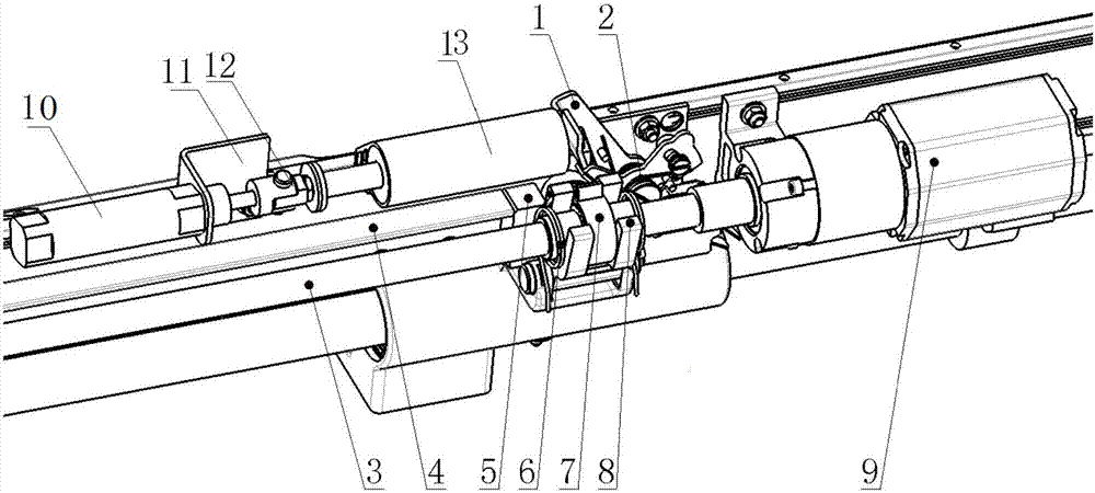
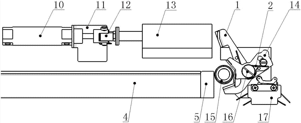
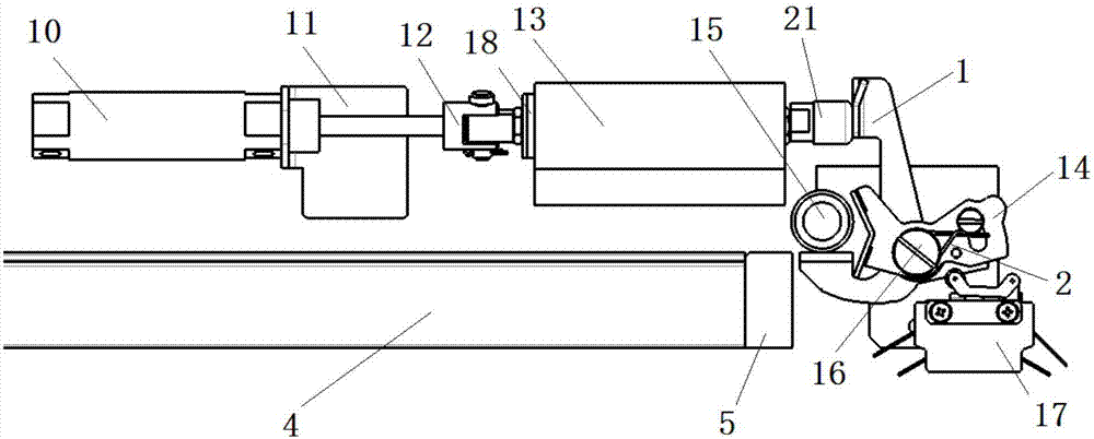
[0018] like figure 1 , figure 2 and image 3 As shown, the emergency unlocking device for the rail transit vehicle door system of the present invention includes an unlocking bracket 1, a return torsion spring 2, a screw mandrel 3, a slideway 4, a wedge 5, a locking torsion spring 6, a nut assembly 7, Transmission frame 8, motor 9, cylinder 10, cylinder bracket 11, connection assembly 12, support frame 13, linkage frame 14, roller 15, unlocking shaft 16, switch assembly 17, retaining ring 18, unlocking spring 19, anti-friction ring 20 , buffer head 21 and pull rod 22, described slideway 4 is horizontally installed on the top of door leaf, described slideway 4 top is provided with cylinder support 11, and described cylinder 10 is installed on the cylinder support 11, and the piston rod of described cylinder 10 It is connected with the front end of the connection asse...
PUM
Abstract
The invention discloses an emergency unlocking device for a door system. The emergency unlocking device for the door system comprises an assembled unlocking support, a resetting torsional spring, a lead screw, a slide way, a wedge block, a locking torsional spring, a nut assembly, a transmission rack, a motor, an air cylinder, an air cylinder support, a connecting assembly, a support frame, a linkage rack, a roller, an unlocking rotating shaft, a switch assembly, a retainer ring, an unlocking spring, an anti-friction ring, a buffer head and a pull rod. By the emergency unlocking device for the door system, the door system can be ensured to be unlocked automatically under the condition that the door system does not have electricity or gas, so that a door leaf can be unlocked effectively under the emergency condition, and remote electric unlocking can be realized. The emergency unlocking device for the door system has few parts, is simple in structure and convenient to assemble, and has good application prospect.
Description
technical field [0001] The invention relates to the technical field of door system components, in particular to an emergency unlocking device for a door system. Background technique [0002] At present, the door system emergency unlocking devices used in door systems such as rail transit vehicles, bus doors, and rail transit screen doors have complex structures, high costs, difficult maintenance, and no remote unlocking function. For example, in the emergency unlocking device of the existing rail transit vehicle door system, the mechanical structure of the wire rope is used for unlocking. In some applications, due to the limitations of the working conditions and installation conditions, the wire rope unlocking device cannot meet the design requirements. The emergency unlocking device has many parts, complex structure, high cost, and is difficult to maintain; it cannot be unlocked through the electrical unit, and the emergency unlocking function of the door must be realized t...
Claims
Application Information
Patent Timeline
Application Date:The date an application was filed.
Publication Date:The date a patent or application was officially published.
First Publication Date:The earliest publication date of a patent with the same application number.
Issue Date:Publication date of the patent grant document.
PCT Entry Date:The Entry date of PCT National Phase.
Estimated Expiry Date:The statutory expiry date of a patent right according to the Patent Law, and it is the longest term of protection that the patent right can achieve without the termination of the patent right due to other reasons(Term extension factor has been taken into account ).
Invalid Date:Actual expiry date is based on effective date or publication date of legal transaction data of invalid patent.