Light source device and projector

A light source device and light beam technology, applied in projection devices, optics, instruments, etc., can solve problems such as increased manufacturing costs, unfavorable light source devices or miniaturized installation layout of light source devices for projectors, invalid light cannot be used, etc., to achieve control of production Cost, the effect of improving light utilization efficiency

Inactive Publication Date: 2016-09-21
QISDA OPTRONICS (SUZHOU) CO LTD +1
View PDF2 Cites 0 Cited by
  • Summary
  • Abstract
  • Description
  • Claims
  • Application Information

AI Technical Summary

Problems solved by technology

[0003] However, there exists at least a portion of the beam such as figure 1 As shown, the light beam with the angle θ between the light beam L2 and the light beam L3 cannot be used because it cannot be reflected to the reflective surface 121 and becomes invalid light and cannot be utilized. The light beam L3 is the connection line between the intersection point Q1 of the first sealing part 113 and the light emitting part 111 and the light emission center O
To solve this technical problem, the prior art generally adopts the method of adding a r

Method used


Image

  • Light source device and projector
  • Light source device and projector
  • Light source device and projector

Examples


Embodiment 1

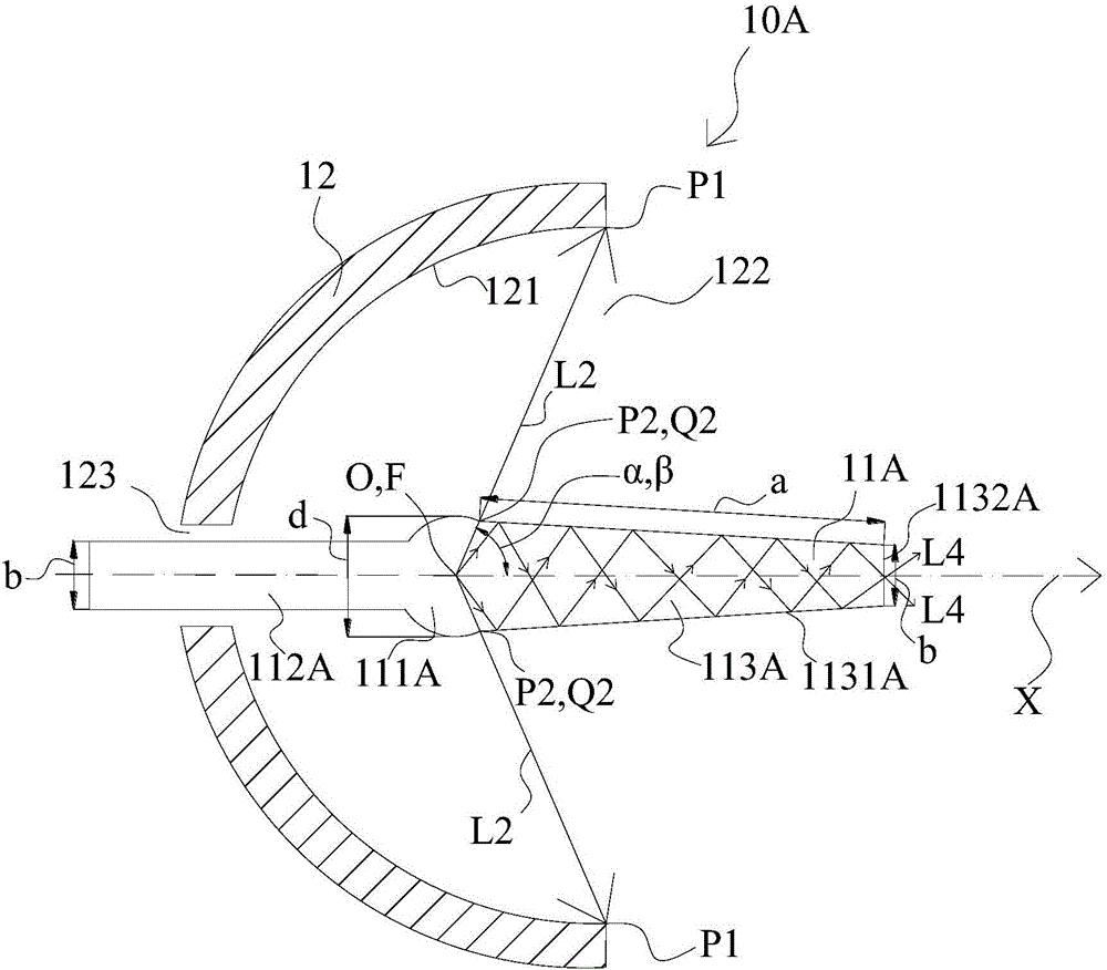
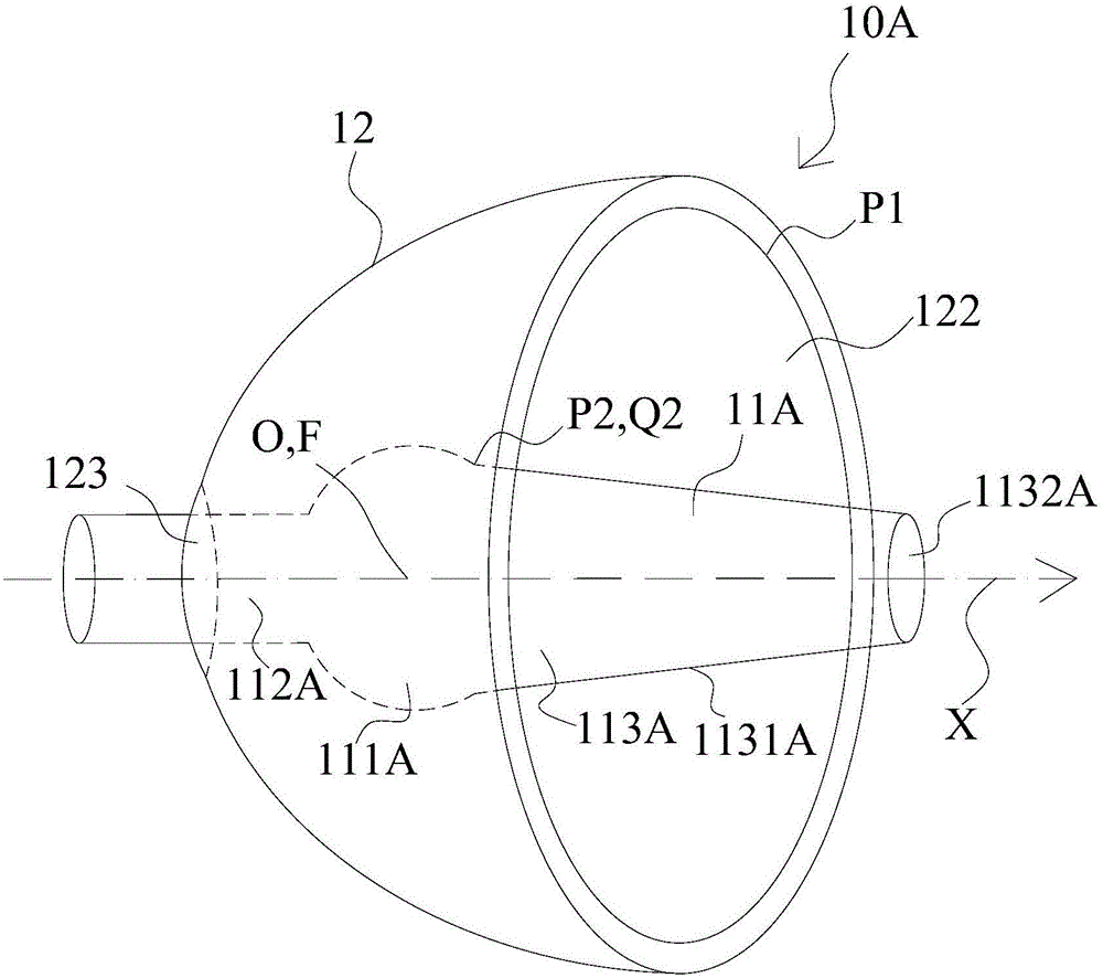
[0026] Embodiment 1 of the present invention will be described below with reference to the drawings. figure 2 is a schematic cross-sectional view of the structure of a light source device 10A provided in Embodiment 1 of the present invention, image 3 It is a three-dimensional schematic diagram of the structure of a light source device 10A provided in Embodiment 1 of the present invention, Figure 4 It is a three-dimensional schematic diagram of the structure of a light emitting tube 11A of a light source device 10A provided in Embodiment 1 of the present invention.

[0027] Such as figure 2 and image 3 As shown, the light source device 10A includes a luminous tube 11A and a reflector 12 that reflects the beam emitted by the luminous tube 11A. The luminous tube 11A is located inside the reflector 12. In other words, the light source device 10A adjusts the beam emitted from the luminous tube 11A to A device that shoots out in a certain direction. In addition, in the pres...

Embodiment 2

[0043] Embodiment 2 of the present invention will be described below with reference to the drawings. Figure 5 It is a schematic cross-sectional view of the structure of a light source device 10B provided in Embodiment 2 of the present invention.

[0044] In the following description, the same structure and the same components as those of the above-mentioned first embodiment are given the same reference numerals, and their detailed descriptions are omitted or simplified.

[0045] In Example 2, such as Figure 5 As shown, the light source device 10B includes a luminous tube 11B and a reflector 12 that reflects the light beam emitted by the luminous tube 11B. The luminous tube 11B is located inside the reflector 12. In other words, the light source device 10B adjusts the light beam emitted from the luminous tube 11B to A device that shoots out in a certain direction. In addition, in the present invention, the light beam emitting direction of the light source device 10B is show...


PUM


Abstract

The invention provides a light source device and a projector. The light source device comprises a light-emitting tube and a reflector, wherein the light-emitting tube comprises a light-emitting part, a first seal part and a second seal part; the light-emitting part emits light beams; the first seal part extends towards a front end side from the light-emitting part; the second seal part extends towards a base end side from the light-emitting part; the reflector comprises a reflecting surface for reflecting the light beams emitted from the light-emitting part, and a first opening for emitting the light beams; the first seal part protrudes the first opening; the peripheral surface of the light-emitting part and the peripheral surface of the first seal part are intersected at a first intersection point; the angle formed by the straight line of the first intersection point and the central point of the light-emitting part and the front end side part of a center shaft of the light-emitting tube is a first angle; the end part of the front end side of the reflecting surface of the reflector is a boundary point; the angle formed by the straight line of the boundary point and the central point of the light-emitting part and the front end side part of the center shaft of the light-emitting tube is a second angle; and the first angle is not smaller than the second angle, so that one part of light beams, exceeding the boundary point, emitted from the light-emitting part enter the first seal part.

Description

technical field [0001] The invention relates to a light source device and a projector, in particular to a light source device and a projector that improve the utilization rate of the light source. Background technique [0002] figure 1 It is a schematic diagram of the light source device of a conventional projector. see figure 1 The light source device 10 includes a light emitting tube 11 and a reflector 12. The light emitting tube 11 has a light emitting portion 111 in a substantially spherical shape. Electrodes (not shown) are arranged in the light emitting portion 111, and the light emitting portion 111 is formed by forming an electric arc between the electrodes. emit light. The first sealing part 113 is cylindrical and is arranged on the front side of the light emitting part 111. The second sealing part 112 is cylindrical and is integrally arranged on the rear side of the light emitting part 111. The light emission center O of the light emitting part 111 and the refle...

Claims


Application Information

Patent Timeline
IPC IPC(8): G03B21/20
CPCG03B21/20G03B21/2006G03B21/2066
Inventor 萧启宏
Owner QISDA OPTRONICS (SUZHOU) CO LTD
Why Eureka
Try Eureka