Small-size broadband antenna

A broadband antenna and microstrip line technology, applied in the field of miniaturized broadband antennas, can solve the problem that the antenna cannot take into account the miniaturization and broadbandization, and achieves the advantages of shielding backward radiation and external interference, smooth input impedance, and reducing the weight of the antenna. Effect

Active Publication Date: 2016-09-21
GUILIN UNIV OF ELECTRONIC TECH
View PDF5 Cites 3 Cited by
  • Summary
  • Abstract
  • Description
  • Claims
  • Application Information

AI Technical Summary

Problems solved by technology

[0004] The technical problem to be solved by the present invention is the problem that existing antennas cannot take into account both miniaturization and broadband, and a miniaturized broadband antenna is provided to reduce the size of the antenna and meet the detection requirements of the system for targets

Method used


Image

  • Small-size broadband antenna
  • Small-size broadband antenna
  • Small-size broadband antenna

Examples


Embodiment Construction

[0025] In order to make the object, technical solution and advantages of the present invention clearer, the present invention will be described in further detail below in conjunction with specific embodiments and with reference to the accompanying drawings. It should be noted that the directional terms mentioned in the embodiments, such as "upper", "lower", "left", "right", "front", "rear", etc., are only referring to the directions of the drawings. Therefore, the directions used are only for illustration and are not intended to limit the protection scope of the present invention.

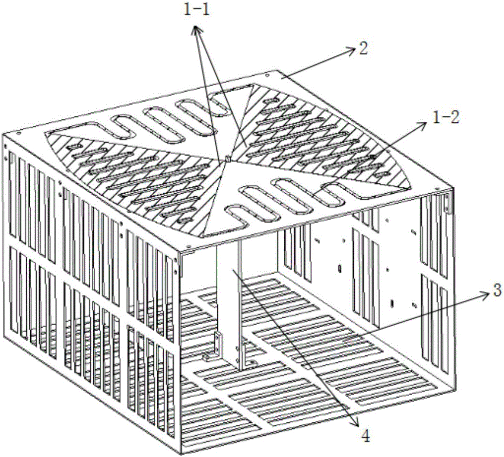
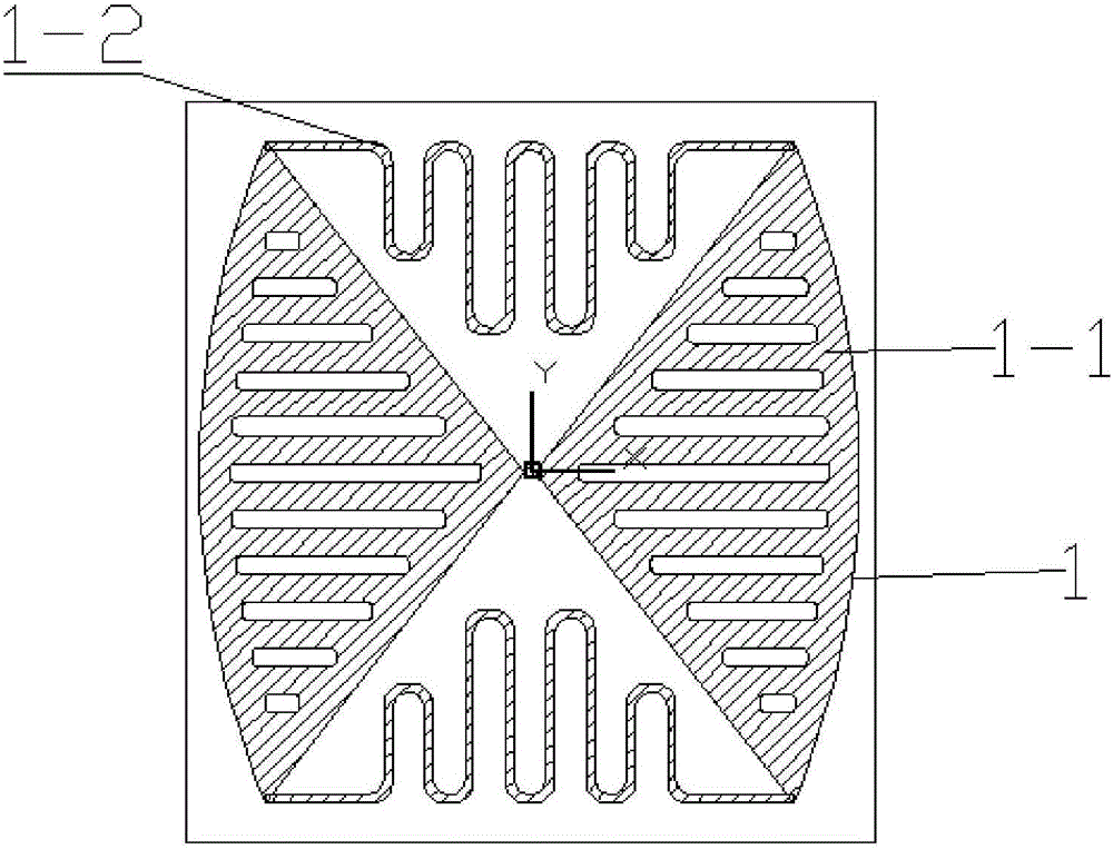
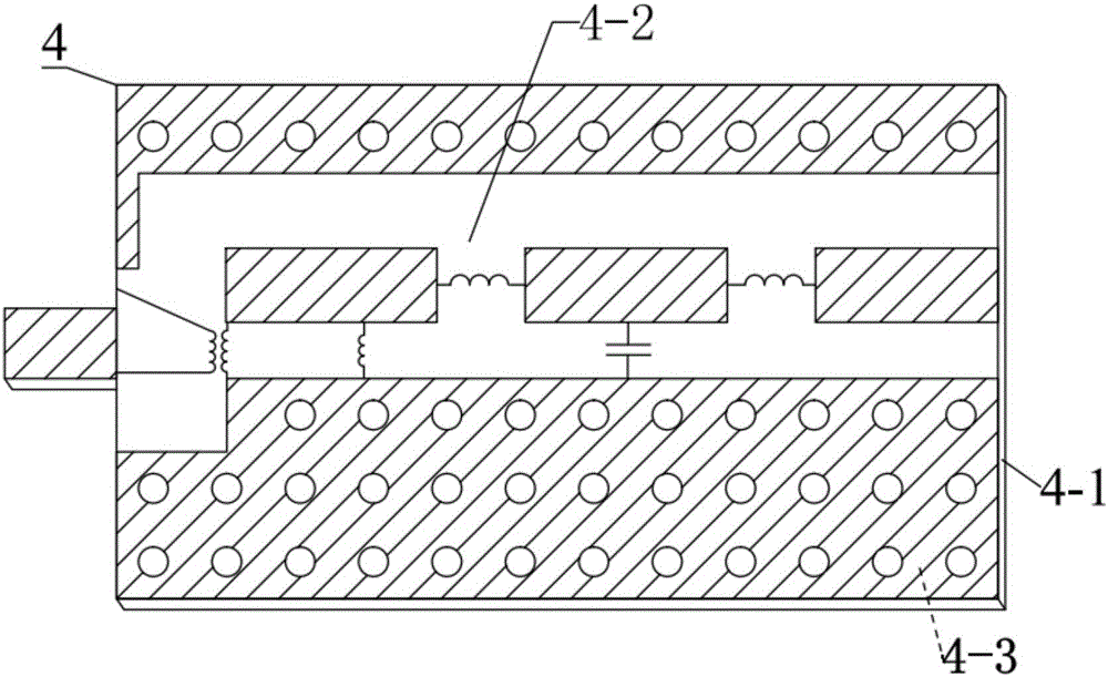
[0026] In an exemplary embodiment of the present invention, a miniaturized broadband antenna is proposed, such as figure 1 As shown, it consists of a radiator 1, an insulating dielectric substrate 2, a metal back cavity 3 and a matching device 4.

[0027] The radiator 1 is made of metal material and printed on the upper surface of the insulating dielectric substrate 2 in a planar shape. The mater...


PUM


Abstract

The invention discloses a small-size broadband antenna, and the antenna comprises a radiator, an insulating dielectric substrate, and a metal back cavity. The metal back cavity is a U-shaped cavity which is formed by one lower bottom surface and two opposite side walls (left and right). The insulating dielectric substrate covers a top surface opening of the metal back cavity. The radiator is shaped like a plane, and is printed on the upper surface of the insulating dielectric substrate. The radiator consists of two fan-shaped units and two microstrip lines. The top points of the two fan-shaped units form feed points of the radiator. The two fan-shaped units are symmetrically distributed at the left and right sides of the insulating dielectric substrate, and the feed points of the two fan-shaped units are opposite and are separated by a certain distance. Each microstrip line is a bent extending line. Two ends of each microstrip line are respectively connected to the bottom end points of the two fan-shaped units at the same side. The two microstrip lines are symmetrically distributed at front and back sides of the insulating dielectric substrate. According to the invention, the size of the antenna is reduced, and the antenna meets the detection requirements of a system for a target.

Description

technical field [0001] The invention relates to the technical field of antennas, in particular to a miniaturized broadband antenna. Background technique [0002] In recent years, due to the rapid development of electronic space technology, the types and forms of antennas used in equipment are increasing, and the requirements for their electrical performance are also increasing. Early antennas, such as blade antennas, single (di) pole antennas, and loaded rod antennas, have problems of narrow bandwidth and large size, which can no longer meet the current use requirements. The important technology to promote the miniaturization and broadbandization of antennas has become a research hotspot and trend, especially in the field of ultrashort wave antennas. [0003] With the maturity of all aspects of UAV technology, its use is becoming more and more extensive, and its combat effectiveness is becoming more and more prominent. As an indispensable part of wireless communication, th...

Claims


Application Information

Patent Timeline
Patent Type & Authority Applications(China)
IPC IPC(8): H01Q1/36H01Q1/50
CPCH01Q1/36H01Q1/50
Inventor 曹卫平曹颖楠李思敏王定雄
Owner GUILIN UNIV OF ELECTRONIC TECH
Why Eureka
Try Eureka