Integrated C-shaped wire clamp

A technology of creating through wires and clamping seats, applied in the direction of clamping/spring connection, electrical components, circuits, etc., which can solve the problems of untargeted loosening, inconvenient operation, and inability to achieve the effect of overcoming the cumbersome installation process

Active Publication Date: 2016-09-21
临泉县卡天下电子商务有限公司
View PDF3 Cites 1 Cited by
  • Summary
  • Abstract
  • Description
  • Claims
  • Application Information

AI Technical Summary

Problems solved by technology

Although the structure is firmly crimped, it can only be used once during maintenance operations. During the second construction, it is necessary to bite off the wire or pry up the top pressure block to deform, discard the structure, and use a new wire clamp to re-construct , so there is a problem of material waste. Since the clamp adopts structural deformation and crimping, it cannot be used after maintenance. At the same time, because it needs to be crimped on the top pressure block, it requires a lot of force on the structure, and it is operated in high-altitude operations. Extremely inconvenient and low safety performance for construction workers
In addition, the above-mentioned common Chuangtong clamps all use the top pressure block to fasten the wires on both sides at the same time. When one of the wires needs to be replaced, the nut in the middle needs to be loosened to loosen the top pressure block in the middle, resulting in two The wires on both sides are all loose, and it is impossible to loosen one of the conductive wires without affecting the other wire
Finally, ordinary Chuangtong cable clamps are divided into C-shaped clamp seat, top pressure block, and bolts and nuts. They are assembled together with the wires when in use. It is troublesome to use. When wiring at high altitudes, you have to hold multiple parts separately. , affect hand flexibility, inconvenient operation

Method used


Image

  • Integrated C-shaped wire clamp
  • Integrated C-shaped wire clamp
  • Integrated C-shaped wire clamp

Examples


Embodiment 1

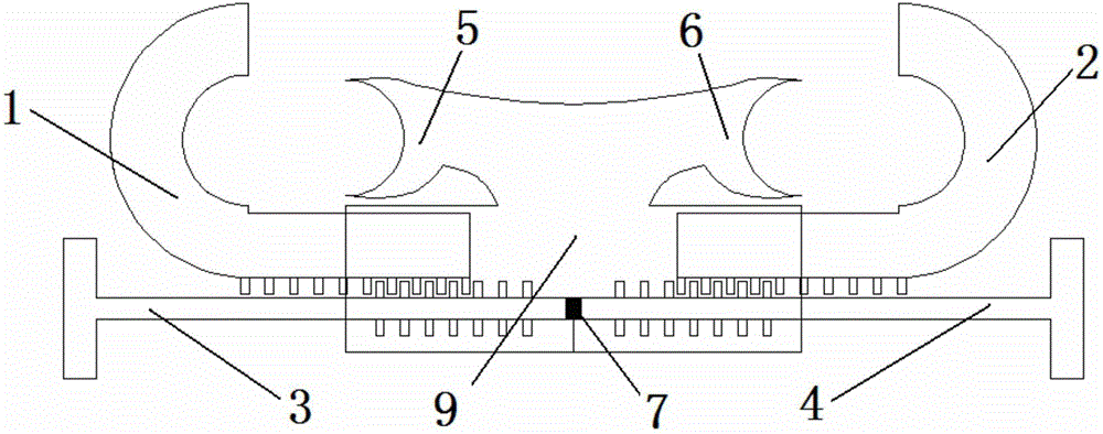
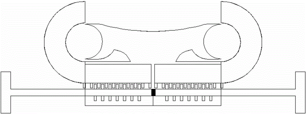
[0022] An integrated Chuangtong clamp, including a clamp seat, a J-shaped left movable clamp block 1, a J-shaped right movable clamp block 2, a left screw rod 3 and a right screw rod 4,

[0023] Described holder comprises left fixed wire slot arm 5, right fixed wire slot arm 6 and box-shaped base 9, and left fixed wire slot arm 5 and right fixed wire slot arm 6 are fixed on the top of box-shaped base 9,

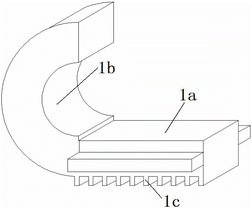
[0024] There are multiple rows of teeth 1c below the straight part of the J-shaped left movable clamp block 1 and the J-shaped right movable clamp block 2, and are respectively installed in the inner cavity of the box-shaped base 9 from both ends thereof,

[0025] Described left screw rod 3 and right screw rod 4 are respectively installed in its inner cavity from the two ends of box-shaped base 9, and the screw teeth of left screw rod 3 and right screw rod 4 are connected with J-shaped left movable clamp block 1 and J-shaped right movable clamp block respectively. 2 Teeth mes...


PUM


Abstract

The invention provides an integrated C-shaped wire clamp, which comprises a clamp base, a J-shaped left movable clamping block, a J-shaped right movable clamping block, a left screw rod and a right screw rod, wherein the clamp base comprises a left fixed wiring duct arm, a right fixed wiring duct arm and a box-shaped base; the left fixed wiring duct arm and the right fixed wiring duct arm are fixed at the upper part of the box-shaped base; multiple rows of teeth are arranged at the lower parts of the straight line parts of the J-shaped left movable clamping block and the J-shaped right movable clamping block and are arranged in an inner cavity from two ends of the box-shaped base separately; the left screw rod and the right screw rod are arranged in the inner cavity from two ends of the box-shaped base separately; and threads of the left screw rod and the right screw rod are meshed with the teeth at the lower parts of the straight line parts of the J-shaped left movable clamping block and the J-shaped right movable clamping block respectively. Wiring ducts on the left side and the right side independently work and can be individually conducted when installed or dismantled, and when one guide wire is operated, the state of the other guide wire is not affected. Furthermore, various parts are combined and installed into a whole for use, so that the operation is simple and convenient.

Description

technical field [0001] The invention relates to electric equipment, in particular to an integrated break-through wire clip. Background technique [0002] Chuangtong wire clamp is a professional wire clamp used for power wiring. It is mainly composed of two top pressure blocks that bite each other and arc-shaped baffles on both sides. When operating, use a crimping tool to press down the top pressure block, and the wire The fitting structure composed of the top pressing block is fitted between the arc-shaped baffles on both sides, and the wires are crimped by structural deformation. Although the structure is firmly crimped, it can only be used once during maintenance operations. During the second construction, it is necessary to bite off the wire or pry up the top pressure block to deform, discard the structure, and use a new wire clamp to re-construct , so there is a problem of material waste. Since the clamp adopts structural deformation and crimping, it cannot be used aft...

Claims


Application Information

Patent Timeline
Patent Type & Authority Applications(China)
IPC IPC(8): H01R11/09H01R4/42
CPCH01R4/42H01R11/09
Inventor 不公告发明人
Owner 临泉县卡天下电子商务有限公司
Why Eureka
Try Eureka