
Fixture

A jig and cable technology, applied in electrical components, circuits, connections, etc., to reduce carding time and improve welding quality and efficiency

Active Publication Date: 2018-04-13
湖南铭基高科电子有限公司
View PDF5 Cites 0 Cited by
  • Summary
  • Abstract
  • Description
  • Claims
  • Application Information

AI Technical Summary

Problems solved by technology

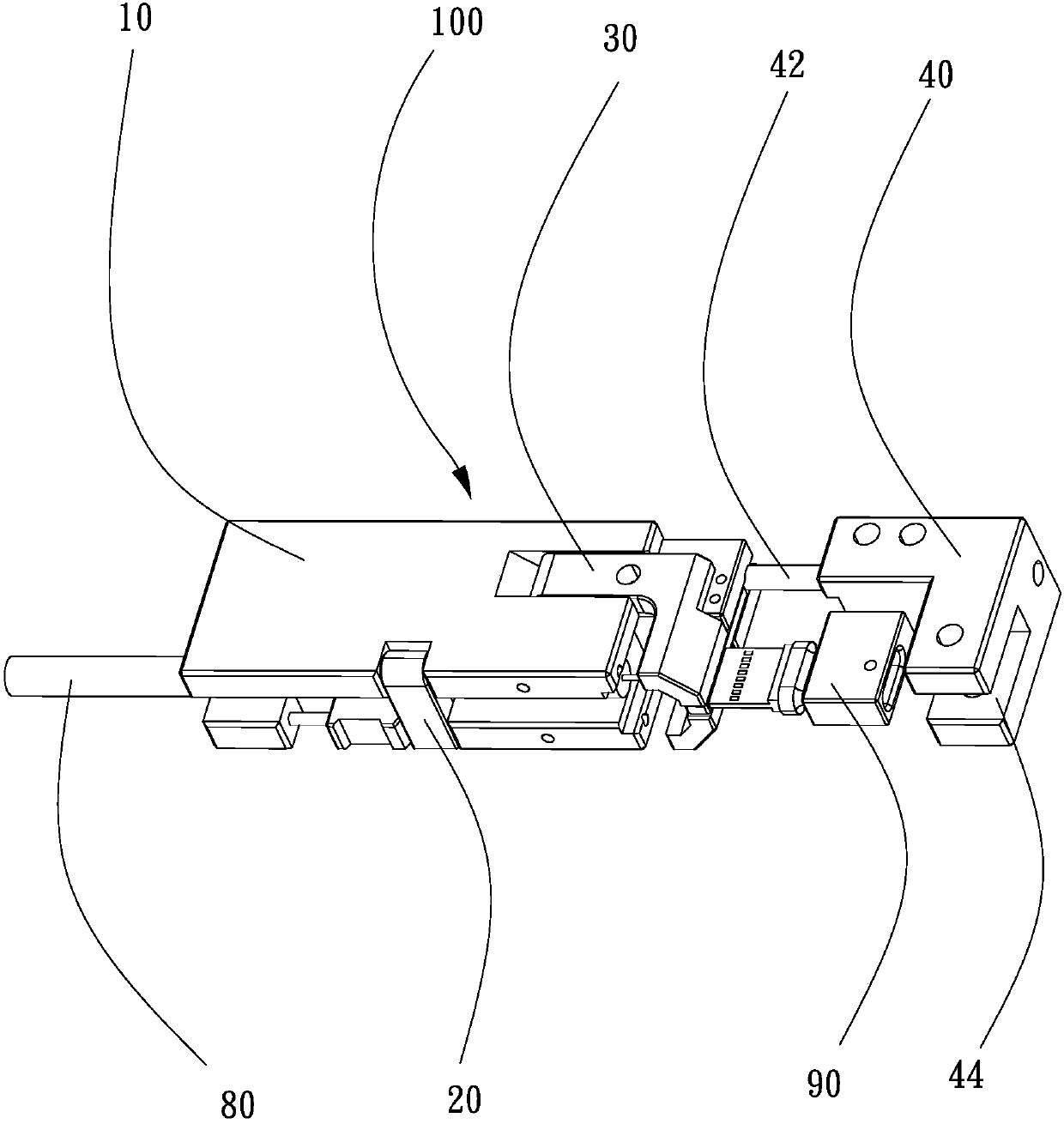
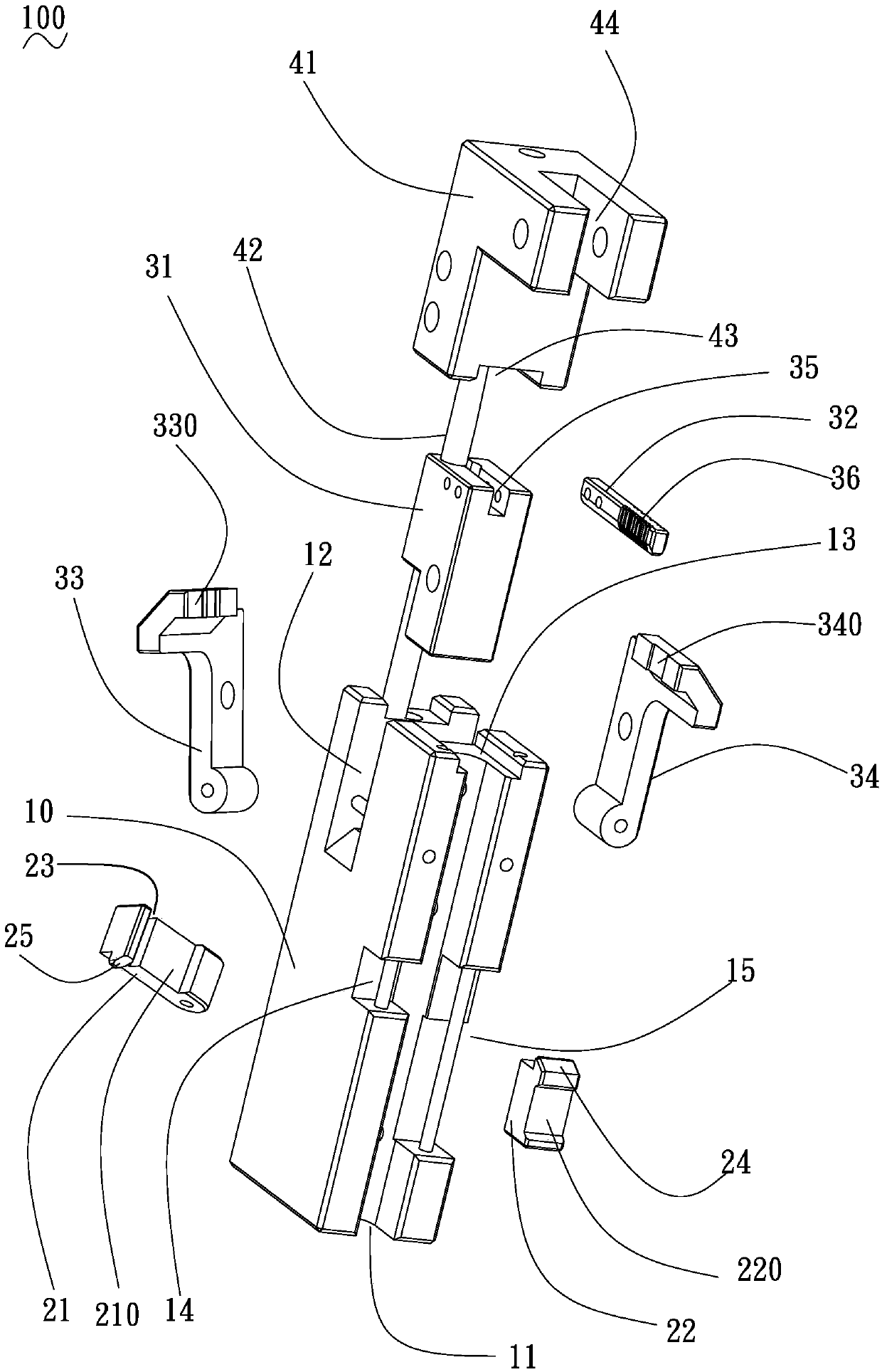
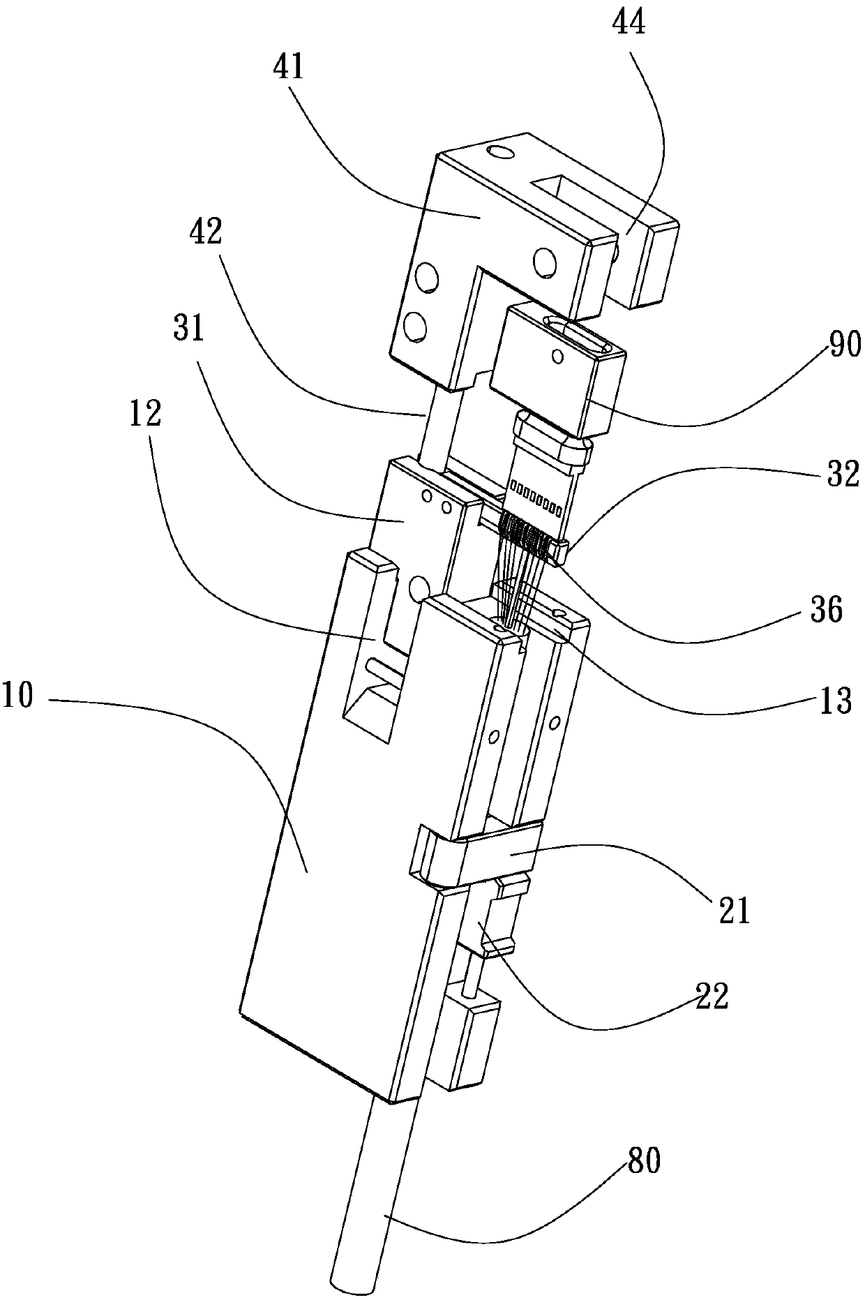
[0003] Based on this, it is necessary to provide a connector welding fixture with simple structure and accurate cable positioning to improve welding quality and efficiency in view of the problems existing in the current traditional technology

Method used


Image

  • Fixture
  • Fixture
  • Fixture

Examples


Embodiment Construction

[0019] In order to facilitate the understanding of the present invention, the present invention will be described more fully below with reference to the associated drawings. Preferred embodiments of the invention are shown in the accompanying drawings. However, the present invention can be embodied in many different forms and is not limited to the embodiments described herein. On the contrary, these embodiments are provided to make the understanding of the disclosure of the present invention more thorough and comprehensive.

[0020] It should be noted that when an element is referred to as being “fixed” to another element, it can be directly on the other element or there can also be an intervening element. When an element is referred to as being "connected to" another element, it can be directly connected to the other element or intervening elements may also be present.

[0021] Unless otherwise defined, all technical and scientific terms used herein have the same meaning as...


PUM


Abstract

The invention relates to a jig, which is used for fixing a connector and cables, so as to make wire cores in the cables to be welded on a circuit board of the connector correspondingly. The jig comprises a base, a self-locking component installed at the side of the base, a cable positioning component installed at the end of the base, and a moveable support leaning against the cable positioning component; the base is provided with a guide groove, a first mounting groove and a second mounting groove; and the guide groove is used for placing the cables. The jig is composed of the base, the moveable support, the cable positioning component and other modules, therefore, the connector and the cables are fixed on one base, and the cables are orderly combed through a trunking of the cable positioning component, so that the cables can be corresponding to metal terminals of the connector one to one, and the time of combing the cables can be greatly reduced; and moreover, a slide connecting rod brake principle is used, thus spatial positions of the connector and the cables can be freely adjusted, thereby changing a complicated cable combing process into a simple welding scheme, and improving the welding quality and efficiency.

Description

technical field [0001] The invention relates to the field of fixtures, in particular to a fixture for positioning welding of connectors. Background technique [0002] As a tool in the manufacturing process of electronic equipment, jigs are often used for pre-positioning in the electrical connector positioning welding process to avoid misalignment during the welding process and improve welding quality. The electrical connector includes a connector body and a cable. When the cable is welded to the connector body, the connector and the cable are generally separately fixed on the jig, and then the cable is fixed by adjusting the positions of the respective bases. The upper wire core is welded with the corresponding metal terminal on the connector; in the above welding method, the connector is double-sided welding, and the connector and the cable need to be turned over, and multiple wires are easy to entangle with each other, and the wire core will be entangled during welding. T...

Claims


Application Information

Patent Timeline
Patent Type & Authority Patents(China)
IPC IPC(8): H01R43/00H01R43/02
CPCH01R43/00H01R43/02H01R43/0263
Inventor 沈传祥
Owner 湖南铭基高科电子有限公司
Learn More