A tool for adjusting the discharge gap between the neutral point of the main transformer and the arrester
A technology of discharge gap and main transformer, applied in the field of transformers, can solve the problems of difficulty in finding the level of the box ruler, measurement data error, low reliability, etc., and achieve the effects of safe and reliable fixed connection, construction safety, and quick installation and disassembly.
- Summary
- Abstract
- Description
- Claims
- Application Information
AI Technical Summary
Problems solved by technology
Method used
Image
Examples
Embodiment 1
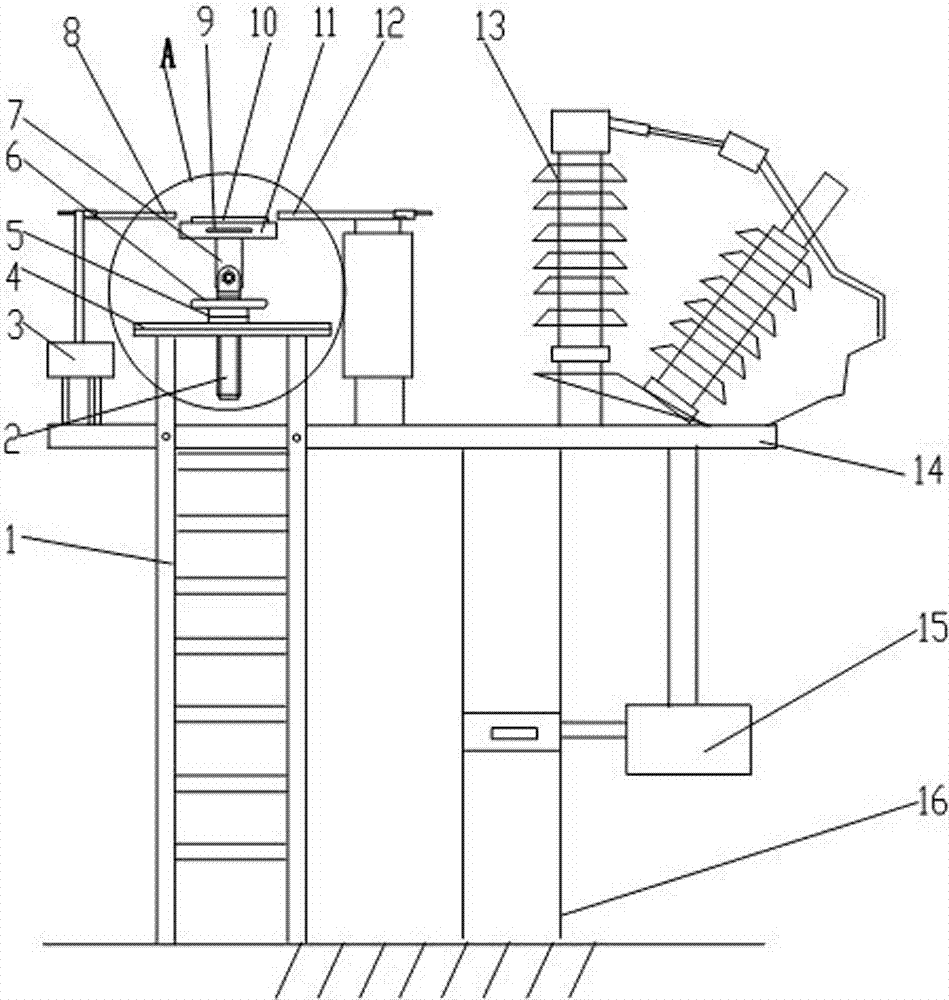
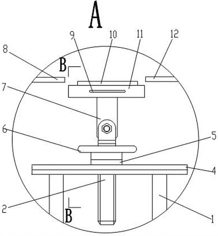
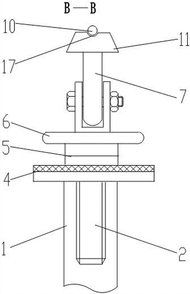
[0015] Embodiment 1: A tool for adjusting the discharge gap between the neutral point of the main transformer and the lightning arrester, including a discharge gap adjustment rod 10, a chute plate 11, a lifting mechanism, a bracket 7, a workbench 4, and a ladder 1; The discharge gap adjustment rod 10 is located in the transverse groove 17 on the upper end surface of the chute plate 11, the lower end of the chute plate 11 is provided with a bracket 7 hinged with the lifting mechanism, and the workbench 4 is fixed on the upper end of the ladder 1, so The lifting mechanism is located on the workbench 4. The discharge gap adjusting rod 10 is provided with a length adjusting mechanism. The length adjustment mechanism of the discharge gap adjusting rod 10 includes a sleeve 19 and two screw rods 18, the two screw rods 18 are respectively located at two ends of the sleeve 19, and each screw rod 18 is connected with the sleeve 19 through threads. A level 9 is also included, and the le...
Embodiment 2
[0016] Embodiment 2: A tool for adjusting the discharge gap between the neutral point of the main transformer and the lightning arrester, including a discharge gap adjustment rod 10, a chute plate 11, a lifting mechanism, a bracket 7, a workbench 4, and a ladder 1; The discharge gap adjustment rod 10 is located in the transverse groove 17 on the upper end surface of the chute plate 11, the lower end of the chute plate 11 is provided with a bracket 7 hinged with the lifting mechanism, and the workbench 4 is fixed on the upper end of the ladder 1, so The lifting mechanism is located on the workbench 4. The lifting mechanism is a lead screw type lifting mechanism, including a turntable 6, a bearing seat 5 and a lead screw 2, the turntable 6 is connected to the middle part of the lead screw 2 by threads, and the lower part of the lead screw 2 is inserted into the through hole of the workbench 4 , the bearing seat 5 is installed on the lead screw 2 between the turntable 6 and the w...
PUM
 Abstract
Description
Claims
Application Information
 - R&D
- Intellectual Property
- Life Sciences
- Materials
- Tech Scout
- Unparalleled Data Quality
- Higher Quality Content
- 60% Fewer Hallucinations
Browse by: Latest US Patents, China's latest patents, Technical Efficacy Thesaurus, Application Domain, Technology Topic, Popular Technical Reports.
© 2025 PatSnap. All rights reserved.Legal|Privacy policy|Modern Slavery Act Transparency Statement|Sitemap|About US| Contact US: help@patsnap.com


