

Message sending method and device
A message sending and message technology, applied in the field of network communication, can solve problems such as network delay increase, network failure, device message discarding, etc., to avoid network delay increase and improve stability
- Summary
- Abstract
- Description
- Claims
- Application Information
AI Technical Summary
Problems solved by technology
Method used
Image

Examples
Embodiment Construction
[0018] In order to enable those skilled in the art to better understand the technical solutions in the embodiments of the present invention, and to make the above-mentioned purposes, features and advantages of the embodiments of the present invention more obvious and understandable, the following describes the technical solutions in the embodiments of the present invention in conjunction with the accompanying drawings For further detailed explanation.
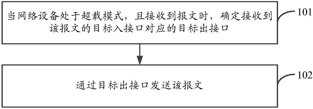
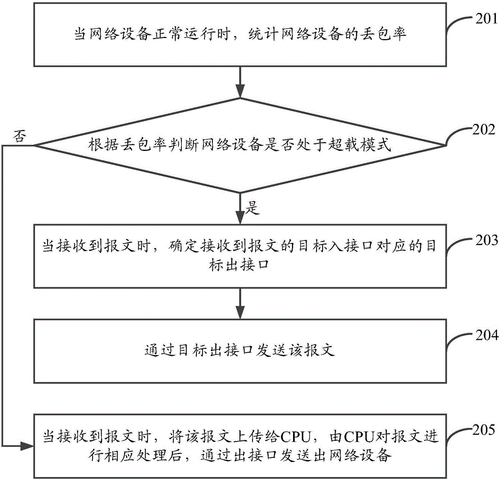
[0019] See figure 1 , is a schematic flowchart of a message sending method provided by an embodiment of the present invention, as shown in figure 1 As shown, the message sending method may include the following steps:
[0020] Step 101. When the network device is in overload mode and receives a message, determine the target output interface corresponding to the target input interface that received the message.
[0021] In the embodiment of the present invention, the above method can be applied to network devices such as IPS e...
PUM
 Abstract
Description
Claims
Application Information