Supercharge Your Innovation With Domain-Expert AI Agents!

Filtering plate

A filter plate and main board technology, applied in the direction of filtration separation, separation methods, chemical instruments and methods, etc., can solve the problems affecting the filtration efficiency of filter presses, and achieve the effects of simple structure, guaranteed filtration efficiency, and reduced waste

Inactive Publication Date: 2016-09-28
NANTONG GOD OF HORSES THREAD
View PDF3 Cites 0 Cited by
  • Summary
  • Abstract
  • Description
  • Claims
  • Application Information

AI Technical Summary

Problems solved by technology

[0002] Filter press is a common equipment used to filter various water-containing materials. With the continuous improvement of the dehydration rate of materials, the filtration pressure adopted by the filter is also increased correspondingly. In the prior art, in the filter chamber of the filter plate The bottom surface is provided with strip-shaped or column-shaped supports at intervals. The gap between the supports becomes the channel of the filtrate. The filter cloth is directly covered on the supports, and the filtrate chamber is formed between the filter cloth and the filter plate. When filtering, the water in the material

Method used


Image

  • Filtering plate
  • Filtering plate
  • Filtering plate

Examples


specific Embodiment 1

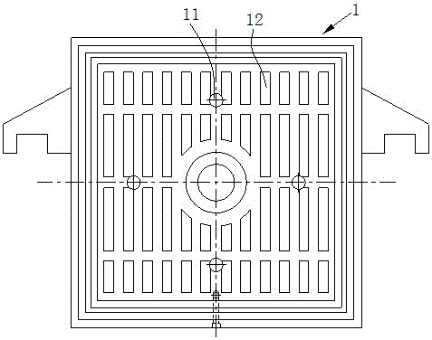
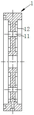
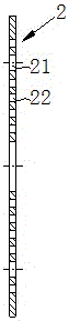
[0021] A filter plate, including a filter main board 1, see figure 1 , figure 2 , set recessed areas on both sides of the filter main board 1 to form filter chambers, refer to image 3 , Figure 4 , the filter plate also includes a porous plate 2, the porous plate 2 is installed in the filter chamber, a support member 12 is arranged between the porous plate 2 and the filter chamber, and the cavity between the porous plate 2 and the filter chamber forms a filtrate chamber; in this implementation In one example, the support 12 is fixedly arranged on the bottom surface of the chamber.

[0022] When filtering, the filtrate produced by filtration can enter the filter chamber through the through hole 22 on the porous plate 2. The size of the through hole 22 on the porous plate 2 can be processed according to different materials and filtration pressures. The optimum diameter of the through hole 22 The range is between 1 mm and 10 mm, and the diameter of the through hole 22 is 1 m...

specific Embodiment 2

[0024] This embodiment is similar in structure to Embodiment 1, refer to Figure 5 , the filter main board 1 is provided with a threaded hole, and the porous plate 2 is provided with a second fastening hole corresponding to the threaded hole, and the fastening screw 33 is screwed in the threaded hole through the second fastening hole and the porous The plate 2 is fastened on the filter main plate 1 . In this embodiment, the support member is fixedly arranged on the perforated plate 2 , and the diameter of the through hole 22 on the perforated plate 2 is 10 mm.

[0025] According to different usage requirements, the perforated plate 2 can also be welded on the filter main board 1 .

[0026] The filter plate of the present invention is simple in structure, and can be modified on the basis of the existing filter plate to reduce waste. After the filter press adopts the filter plate of the present invention, the filter cloth is covered on the porous plate. After passing through t...


PUM

PropertyMeasurementUnit
Diameteraaaaaaaaaa

Abstract

The invention provides a filtering plate which comprises a main filtering plate, wherein a concave area is arranged on each of the two sides of the main filtering plate to form a filtering chamber; the filtering plate further comprises porous plates; each porous plate is mounted in the corresponding filtering chamber; supporting parts are arranged between each porous plate and the corresponding filtering chamber; a filtrate cavity is formed by each porous plate and the cavity of the corresponding filtering chamber; the optimal range of the diameter of through holes is 1-10 mm; the porous plates can be connected onto the main filtering plate in a bolted connection manner, and can also be welded onto the main filtering plate. The filtering plate is simple in structure, and can be transformed on the basis of the conventional filtering plate; according to the filtering plate, the condition that a filtrate can be prevented from being smoothly discharged because filtering cloth is adhered to the bottoms of the filtering chambers of the filtering plate when pressed by materials is avoided.

Description

Technical field: [0001] The invention relates to a filter plate used in a filter press. Background technique: [0002] Filter press is a common equipment used to filter various water-containing materials. With the continuous improvement of the dehydration rate of materials, the filtration pressure adopted by the filter is also increased correspondingly. In the prior art, in the filter chamber of the filter plate The bottom surface is provided with strip-shaped or column-shaped supports at intervals. The gap between the supports becomes the channel of the filtrate. The filter cloth is directly covered on the supports, and the filtrate chamber is formed between the filter cloth and the filter plate. When filtering, the water in the material enters the filtrate cavity through the filter cloth, and then is discharged along the channel between the supports and through the drainage holes on the filter plate; the filter cloth must bear the extrusion of the material, when the filt...

Claims


Application Information

Patent Timeline
IPC IPC(8): B01D25/12
CPCB01D25/12B01D25/215
Inventor 马志宏
Owner NANTONG GOD OF HORSES THREAD
Features
  • R&D
  • Intellectual Property
  • Life Sciences
  • Materials
  • Tech Scout
  • Unparalleled Data Quality
  • Higher Quality Content
  • 60% Fewer Hallucinations
Learn More