Pipe end forming machine

A forming machine and forming mechanism technology, applied in metal processing equipment, feeding devices, positioning devices, etc., can solve the problems of reducing processing accuracy, affecting processing accuracy, and inability to clamp processing, so as to reduce interference and improve processing accuracy Effect

Inactive Publication Date: 2016-09-28
和和机械(张家港)有限公司
View PDF11 Cites 7 Cited by
  • Summary
  • Abstract
  • Description
  • Claims
  • Application Information

AI Technical Summary

Problems solved by technology

[0004] The pipe end forming machine with the above structure has the following disadvantages: 1. In order to facilitate the placement of the pipe to be formed, the clamping frame is in the shape of a U-shaped opening with one side sunken inward, but the other side of the clamping frame is a closed structure. When some bent pipes that have been bent and formed before are used for pipe end forming, the bending part of the bent pipe is likely to interfere with the clamping frame, resulting in the inability to clamp and process; 2. The forming cylinder, mold tube seat and clamping frame are independently Fixed installation on the frame, there is a cumulative error during the installation process, which reduces the machining accuracy, and the forming cylinder will shake during the working process, which will also affect the machining accuracy

Method used


Image

  • Pipe end forming machine
  • Pipe end forming machine
  • Pipe end forming machine

Examples


Embodiment Construction

[0015] The technical solutions of the present invention will be further described in detail below in conjunction with the accompanying drawings and preferred embodiments.

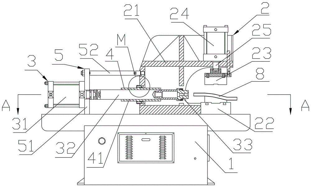
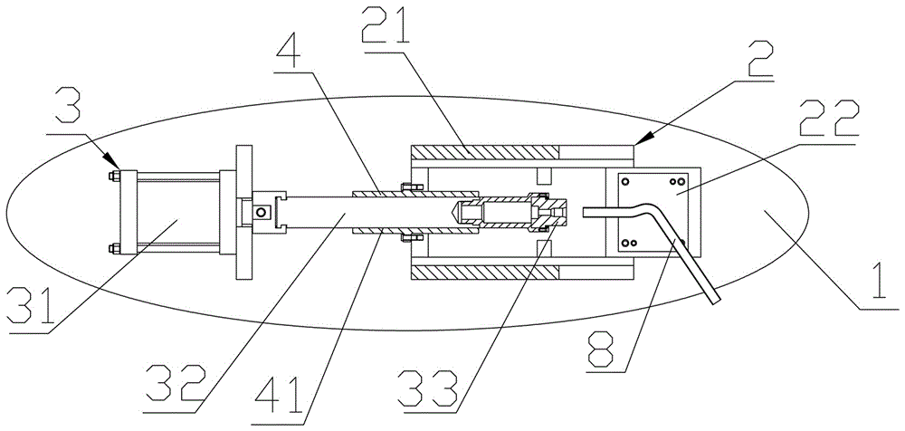
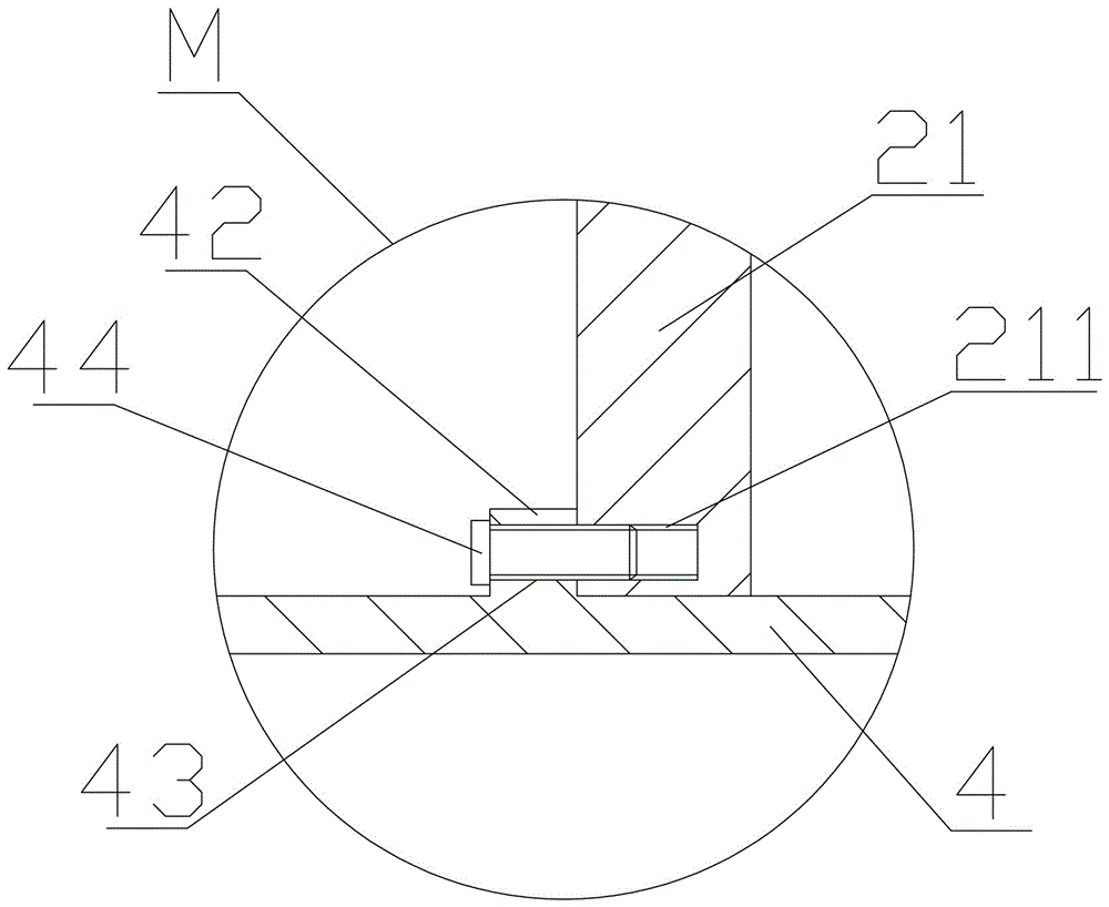
[0016] Such as figure 1 , figure 2 As shown, the pipe end forming machine includes: a frame 1, a clamping mechanism 2 is provided on the frame 1, and a forming mechanism 3 is provided on one side of the clamping mechanism 2, and the clamping mechanism 2 includes a frame fixedly installed on the frame. 1, one end of the clamping frame 21 away from the forming mechanism 3 is recessed inwardly and forms a clamping gap for clamping the pipe 8 to be formed, and the side walls on both sides of the clamping gap are respectively provided with Can avoid the gap of the curved pipe, so that the clamping gap on the clamping frame 21 forms a structure that runs through the front and back without hindering the clamping of the curved pipe. Correspondingly, an upper clamping die 23 is installed on the top, and a clampin...


PUM


Abstract

The invention discloses a pipe end forming machine in the field of pipe machining equipment. The pipe end forming machine comprises a rack, wherein a clamping mechanism is arranged on the rack, a forming mechanism is arranged at one side of the clamping mechanism, the clamping mechanism comprises a clamping frame; one end, far away from the forming mechanism, of the clamping frame sinks inwards to form a clamping notch; gaps are respectively formed in side walls at two sides of the clamping notch, so that the clamping notch in the clamping frame is of a front and back through open structure; a lower clamping die is arranged at the bottom of the clamping notch, an upper clamping die is arranged above the lower clamping die, a clamping cylinder is fixedly arranged on the clamping frame, and under the action of the clamping cylinder, the upper clamping die can achieve die assembly or separation with the lower clamping die; the forming mechanism comprises a forming cylinder, a piston rod of the forming cylinder can extend to the direction of the clamping notch and is movably supported in the clamping frame; and a forming die is arranged at an end part of the piston rod of the forming cylinder. The pipe end forming machine has the advantages of being high in machining precision and capable of avoiding interference between a bent pipe and a machining bench.

Description

technical field [0001] The invention relates to the field of pipe material processing equipment, in particular to a pipe end forming equipment. Background technique [0002] The pipe end forming machine is a kind of end surface forming processing equipment for pipe workpieces, which is suitable for forming and processing various shapes of pipe joints, automobile oil pipes, air pipes, water pipes, and air-conditioning pipe joints. A pipe end forming machine commonly used in the industry at present, its structure includes: a frame, a clamping mechanism is arranged on the frame, a forming mechanism is arranged on one side of the clamping mechanism, and the clamping mechanism includes a The upper clamping frame, one side of the clamping frame is recessed inwardly to form a U-shaped notch for clamping the pipe, the bottom of the U-shaped notch is fixedly installed with the lower clamping die, and the top of the U-shaped notch is correspondingly movable. On the upper clamping mol...

Claims


Application Information

Patent Timeline
Patent Type & Authority Applications(China)
IPC IPC(8): B21D19/00B21D43/00
CPCB21D19/00B21D43/003
Inventor 黄俊杰
Owner 和和机械(张家港)有限公司
Why Eureka
Try Eureka