
A die head driving device of an automatic terminal machine

A technology of automatic terminal machine and driving device, which is applied in the direction of contact piece manufacturing, etc., can solve the problems of metal reed sticking, manual removal, low efficiency, etc., and achieves the effect of simple structure, low cost, and extended range of activities

Active Publication Date: 2017-11-28
KEY BOW ELECTRONICS RIZHAO
View PDF4 Cites 0 Cited by
  • Summary
  • Abstract
  • Description
  • Claims
  • Application Information

AI Technical Summary

Problems solved by technology

The template of the existing terminal machine is connected by a single cylinder, and only one punching process can be completed at a time, and the efficiency is low
In addition, the existing formwork uses flat-headed columns, which may easily cause the metal reeds to stick together and need to be removed manually, which is quite troublesome

Method used


Image

  • A die head driving device of an automatic terminal machine
  • A die head driving device of an automatic terminal machine
  • A die head driving device of an automatic terminal machine

Examples


Embodiment Construction

[0016] The preferred embodiments of the present invention will be described in detail below in conjunction with the accompanying drawings, so that the advantages and features of the present invention can be more easily understood by those skilled in the art, so as to define the protection scope of the present invention more clearly.

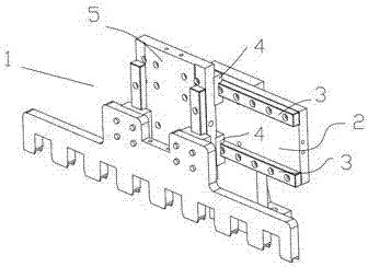
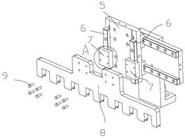
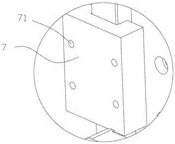
[0017] Such as Figure 1 to Figure 5 As shown, the die head driving device 1 of the automatic terminal machine includes a first driving substrate 2 arranged vertically, and a first sliding rail 3 is respectively provided on the upper and lower sides of the first driving substrate 2, and the first sliding rail 3 are respectively provided with a slidable first sliding seat 4, and the first sliding seat 4 is provided with a detachable second driving substrate 5, and the left and right sides of the second driving substrate 5 are respectively provided with a second sliding rail 6. The second sliding rails 6 are respectively provided with a second slid...


PUM


Abstract

The invention discloses a die head driving device of an automatic terminal crimping machine. The die head driving device of the automatic terminal crimping machine is characterized by comprising a first driving basal plate which is arranged longitudinally; first sliding rail bars are arranged at the upper side and the lower side of the first driving basal plate respectively; a slideable first sliding seat is arranged on each first sliding rail bar; a dismountable second driving basal plate is arranged on the first sliding seats and second sliding rail bars are arranged at the left side and the right side of the second driving basal plate; a second sliding seat is arranged on each second sliding rail bar and a dismountable forming template is arranged on the second sliding seats. According to the device, the whole forming template can move freely in the horizontal position and the longitudinal position by the first sliding rail bars and the second sliding rail bars, so that the movable range of the forming template is greatly expanded, the pressing operation of multiple groups of terminals can be finished at one time by the forming template, and the usability and the reliability of the automatic terminal crimping machine are greatly improved.

Description

technical field [0001] The invention relates to a terminal processing device, more precisely, a die head driving device of an automatic terminal machine. Background technique [0002] Automatic terminal machine is a common metal terminal processing equipment. It uses a special template to mold the metal reed into a preset shape, which is convenient for wire connection. The template of the existing terminal machine is connected by a single cylinder, and only one punching process can be completed at a time, and the efficiency is low. In addition, the existing formwork adopts flat-headed columns, which easily causes the metal reeds to stick together and needs to be removed manually, which is quite troublesome. Contents of the invention [0003] The invention mainly solves the technical problems existing in the prior art, thereby providing a die head driving device of an automatic terminal machine. [0004] Above-mentioned technical problem of the present invention is mainly...

Claims


Application Information

Patent Timeline
Patent Type & Authority Patents(China)
IPC IPC(8): B21D22/06H01R43/16
CPCB21D22/06H01R43/16
Inventor 谢博
Owner KEY BOW ELECTRONICS RIZHAO
Learn More