
Novel imprinting device

A new type of pressure roller technology, applied in printing, printing machines, rotary printing machines, etc., can solve the problems of difficult synchronous movement and pushing of cylinders, poor overprinting accuracy and printing quality, and unbalanced pushing force, so as to improve overprinting accuracy and The effect of print quality

Active Publication Date: 2016-09-28
ZHONGSHAN SOTECH PRINTING MACHINERY CO LTD
View PDF7 Cites 2 Cited by
  • Summary
  • Abstract
  • Description
  • Claims
  • Application Information

AI Technical Summary

Problems solved by technology

[0002] In an embossing machine, it usually includes an embossing roller, a plate roller, and a pushing device that can drive the embossing roller to move and press against the plate roller. The traditional pushing device is mostly a single cylinder, which not only has insufficient pushing force, but also The pressure is unbalanced, and the overprinting accuracy and printing quality are poor. At present, although there are also double-cylinder driving mechanisms to push both ends of the embossing roller at the same time, even if the cylinders of the same specification are used, due to the problem of process accuracy and the layout of the air circuit Different, it is difficult for two cylinders to achieve the effect of synchronous moving and pushing

Method used


Image

  • Novel imprinting device
  • Novel imprinting device
  • Novel imprinting device

Examples


Embodiment Construction

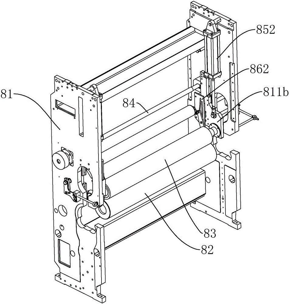
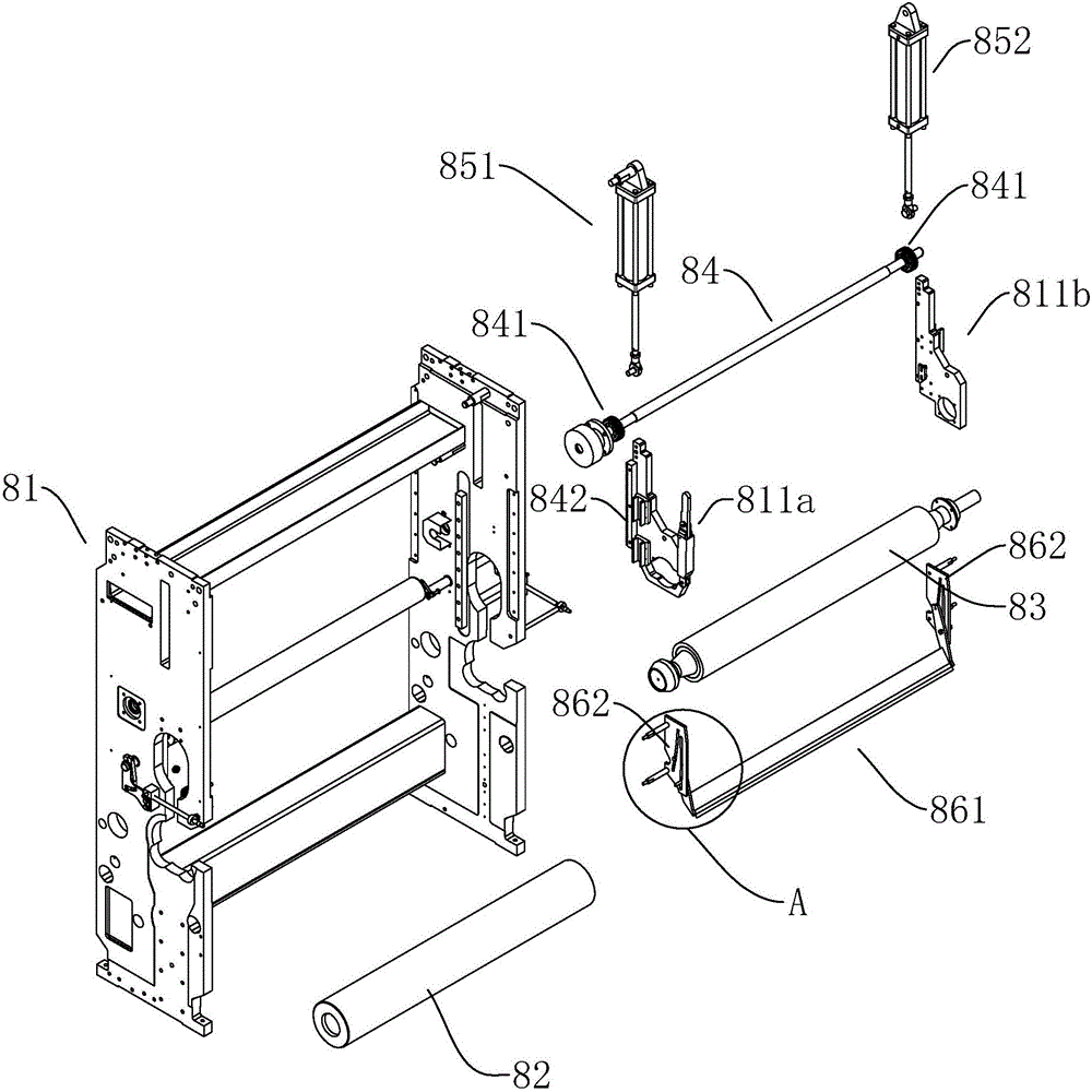
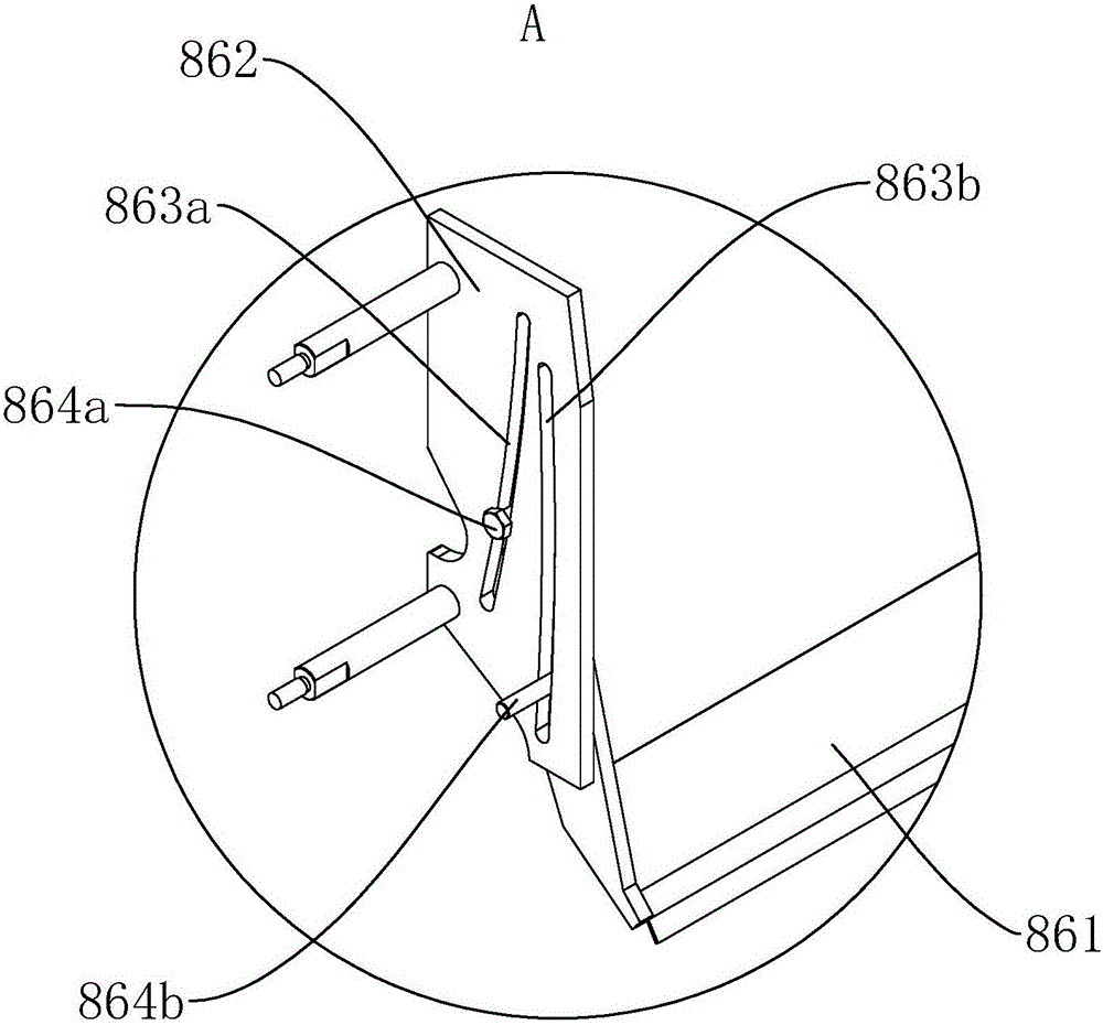
[0020] refer to Figure 1 to Figure 3 , Figure 1 to Figure 3 It is a structural schematic diagram of a specific embodiment of the present invention. As shown in the figure, a new embossing device includes a stand 81, a printing roller 82, a pressing roller 83 and a lifting drive device. The two ends of the printing roller 82 are arranged on the vertical On the frame 81, a left lifting plate 811a and a right lifting plate 811b are slidingly provided on both sides of the stand 81 respectively, and the two ends of the pressure roller 83 are respectively arranged on the left lifting plate 811a and the right lifting plate 811b. A synchronous lifting mechanism is provided between the plate 811a and the right lifting plate 811b, and the lifting drive device can drive the left lifting plate 811a and the right lifting plate 811b to move up and down synchronously relative to the plate roller 82, ensuring that both ends of the pressure roller 83 can be lifted and lowered synchronously ...


PUM


Abstract

The invention discloses a novel imprinting device. The novel imprinting device comprises a vertical rack, a plate roller, a compression roller and a lifting driving device, wherein the two ends of the plate roller are arranged on the vertical rack; a left lifting plate and a right lifting plate are respectively arranged on the two sides of the vertical rack in a sliding manner; the two ends of the compression roller are respectively arranged on the left lifting plate and the right lifting plate; a synchronous lifting mechanism is arranged between the left lifting plate and the right lifting plate; and the synchronous lifting mechanism can drive the left lifting plate and the right lifting plate to synchronously rise, fall and move relative to the plate roller, so that the two ends of the compression roller are guaranteed to synchronously rise, fall and push, and the overprinting precision and printing quality of the imprinting device are improved.

Description

technical field [0001] The present invention relates to printing machine equipment, especially a new embossing device. Background technique [0002] In an embossing machine, it usually includes an embossing roller, a plate roller, and a pushing device that can drive the embossing roller to move and press against the plate roller. The traditional pushing device is mostly a single cylinder, which not only has insufficient pushing force, but also The pressure is unbalanced, and the overprinting accuracy and printing quality are poor. At present, although there are also double-cylinder driving mechanisms to push both ends of the embossing roller at the same time, even if the cylinders of the same specification are used, due to the problem of process accuracy and the layout of the air circuit Different, it is difficult for the two cylinders to truly achieve the effect of synchronous movement and pushing. Contents of the invention [0003] In order to overcome the deficiencies ...

Claims


Application Information

Patent Timeline
Patent Type & Authority Applications(China)
IPC IPC(8): B41F13/008
CPCB41F13/008
Inventor 郭景松秦启雄孟宗发吴文秋黄亚东
Owner ZHONGSHAN SOTECH PRINTING MACHINERY CO LTD
Learn More