Direct connection type shaft-free plate installing structure with safety limiting function

A direct-connected, shaftless technology, used in general parts of printing machinery, printing, printing machines, etc., can solve problems such as adjustment trouble, damage to cylinder components, deformation of printing plate rollers, etc., to prevent damage to cylinder components and increase products. The effect of life and stability improvement

Inactive Publication Date: 2018-03-06
广东汕樟轻工股份有限公司
View PDF0 Cites 1 Cited by
  • Summary
  • Abstract
  • Description
  • Claims
  • Application Information

AI Technical Summary

Problems solved by technology

In the printing process of product packaging, the printing plate roller adjustment mechanism is an integral adjustment of the printing plate roller and its base according to the needs. The adjustment is extremely troublesome and the structure is relatively complicated, which affects the printing work efficiency and Quality, while the printing operation, the stability and overprinting accuracy of the equipment are not high enough to meet customer needs, and there is another problem that the lateral displacement of the printing plate roller is not restricted, resulting in damage to the cylinder assembly, and the printing plate roller is pushed to the Deformation and motor overload damage

Method used


Image

  • Direct connection type shaft-free plate installing structure with safety limiting function
  • Direct connection type shaft-free plate installing structure with safety limiting function
  • Direct connection type shaft-free plate installing structure with safety limiting function

Examples


Embodiment Construction

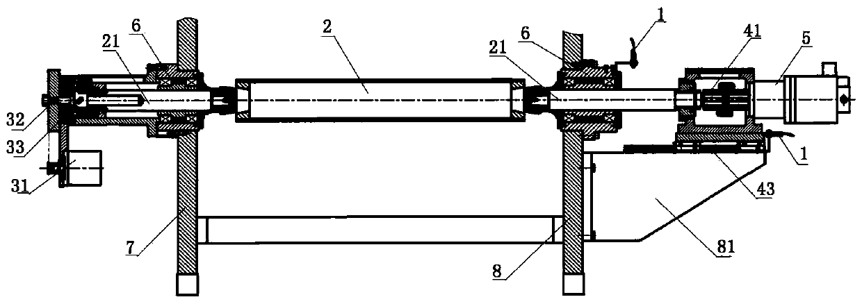
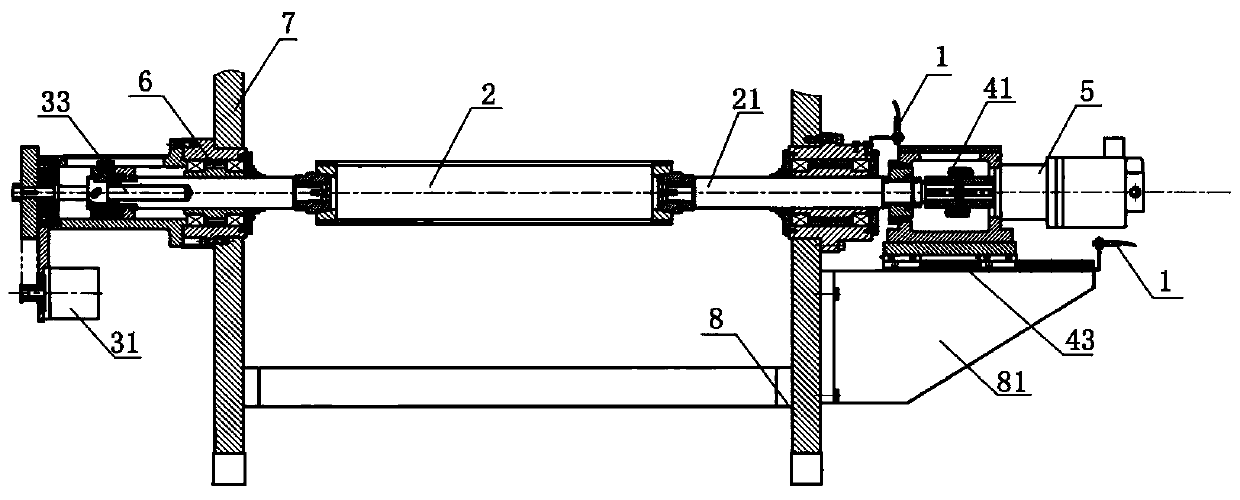
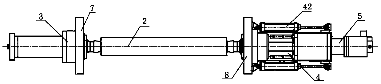
[0018] In order to enable the review committee to have a further understanding of the purpose, features and functions of the present invention, the preferred embodiments are hereby given in detail in conjunction with the drawings as follows:

[0019] refer to Figure 1~3 , is a schematic structural view of the present invention. A direct-connected shaftless plate loading structure with a safety limit, comprising: a limit switch 1, a printing plate roller 2, a first pushing device 3 and a second pushing device 4, the two ends of the printing plate roller 2 They are respectively connected to the left push device 3 and the right push device 4 through the printing plate shaft 21, the described printing plate shaft 21 is installed on the operation surface wallboard 7 and the transmission surface wallboard 8 through the bearing seat 6, and the described limit switch 1 is installed on the first pushing device 3 and / or the second pushing device 4, and the limit switch 1 is respective...


PUM


Abstract

The invention relates to the field of printing plate roller plate loading structure, in particular to a direct-connected shaftless plate loading structure with safety limit. The limit switch mainly includes: a limit switch, a printing plate roller, a first pushing device and a second pushing device, and the two ends of the printing plate roller are respectively connected to the left pushing device and the right pushing device through the printing plate shaft, so The above-mentioned printing plate shaft is installed on the operation surface wallboard and the transmission surface wallboard through the bearing seat, and the above-mentioned limit switch is installed on the first pushing device and/or the second pushing device. The shaftless and shaftless plate loading structure increases the limit switch for printing plate safety, which can not only limit the displacement of the printing plate shaft and the printing plate roller, avoid the occurrence of the printing plate roller falling off, but also effectively prevent the damage of the cylinder assembly and the printing plate The roller is deformed by extrusion, and the transverse correction motor is damaged due to current overload.

Description

technical field [0001] The invention relates to the field of printing plate roller plate loading structure, in particular to a direct-connected shaftless plate loading structure with safety limit. Background technique [0002] At present, with the improvement of the national economy and the development of the printing and packaging industry, the requirements for product packaging are: high-end, exquisite, environmentally friendly, and full of personalization. In the printing process of product packaging, the printing plate roller adjustment mechanism is an integral adjustment of the printing plate roller and its base according to the needs. The adjustment is extremely troublesome and the structure is relatively complicated, which affects the printing efficiency and Quality, while the printing operation, the stability of the equipment and the overprinting accuracy are not high enough to meet customer needs. Another problem is that the lateral displacement of the printing plat...

Claims


Application Information

Patent Timeline
Patent Type & Authority Applications(China)
IPC IPC(8): B41F27/06
CPCB41F27/06
Inventor 李丽辉王有德
Owner 广东汕樟轻工股份有限公司
Why Eureka
Try Eureka