
Direct connection type shaftless lock up structure

A direct-connected, shaftless technology, used in printing, printing machines, general parts of printing machinery, etc., can solve the problems of troublesome adjustment, complex structure, equipment stability and overprinting accuracy, etc., to improve stability, increase The effect of service life

Inactive Publication Date: 2018-03-06
广东汕樟轻工股份有限公司
View PDF0 Cites 1 Cited by
  • Summary
  • Abstract
  • Description
  • Claims
  • Application Information

AI Technical Summary

Problems solved by technology

In the printing process of product packaging, the printing plate roller adjustment mechanism is an integral adjustment of the printing plate roller and its base according to the needs. The adjustment is extremely troublesome and the structure is relatively complicated, which affects the printing efficiency and Quality, while the printing operation, the stability of the equipment and the accuracy of overprinting are not high enough to meet customer needs

Method used


Image

  • Direct connection type shaftless lock up structure
  • Direct connection type shaftless lock up structure

Examples


Embodiment Construction

[0016] In order to enable the review committee to have a further understanding of the purpose, features and functions of the present invention, the preferred embodiments are hereby given in detail in conjunction with the drawings as follows:

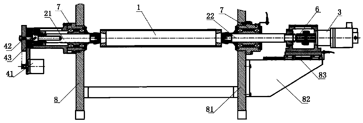
[0017] refer to Figure 1~2 , is shown as the structural representation of the present invention. A direct-connected shaftless plate loading structure, comprising: a printing plate roller 1, a printing plate shaft 2 and a printing plate drive motor 3, the left and right ends of the printing plate roller 1 are connected to the printing plate shaft 2, and the left printing plate shaft The outer end of 21 is provided with a correction motor unit 4, and the outer end of the right printing plate shaft 22 is provided with a cylinder 5, which drives the right printing plate shaft 2 and the printing plate drive motor 3 to move, and the correction motor unit 4 and the cylinder 5 cooperate with each other , so that the printing plate roller 1 can...


PUM


Abstract

The present invention relates to the field of printing plate roller plate loading structure, in particular to a direct-connected shaftless plate loading structure, comprising: a printing plate roller, a printing plate shaft and a printing plate driving motor, and the left and right ends of the printing plate roller are connected The printing plate shaft, the outer end of the left printing plate shaft is equipped with a correction motor unit, and the outer end of the right printing plate shaft is equipped with a cylinder, which drives the right printing plate shaft and the printing plate driving motor to move, and the correction motor unit and the cylinder cooperate with each other. Make the printing plate roller move back and forth laterally for adjustment. The beneficial effects of the present invention are: 1. The direct-connection shaftless plate loading structure adopts only one coupling between the printing plate shaft and the printing plate driving motor, and the printing plate driving motor adopts a low-speed high-torque servo motor, eliminating The transmission backlash inherent in the intermediate deceleration part; 2. The printing plate roller is adjusted by the cooperation of the motor unit and the cylinder so that it can move back and forth laterally, and the cylinder drives the printing plate drive motor and coupling to move along the linear guide rail , The direction and position of the combined force of the cylinder are consistent with the axis of the printing plate, and no additional torque will be generated during operation, thereby improving the stability of the printing operation of the equipment, overprinting accuracy and printing speed, and also increasing the service life of the product.

Description

technical field [0001] The invention relates to the field of printing plate roller plate loading structure, in particular to a direct-connected shaftless plate loading structure. Background technique [0002] At present, with the improvement of the national economy and the development of the printing and packaging industry, the requirements for product packaging are: high-end, exquisite, environmentally friendly, and full of personalization. In the printing process of product packaging, the printing plate roller adjustment mechanism is an integral adjustment of the printing plate roller and its base according to the needs. The adjustment is extremely troublesome and the structure is relatively complicated, which affects the printing work efficiency and Quality, while printing operations, equipment stability and overprinting accuracy are not high enough to meet customer needs. Contents of the invention [0003] The purpose of the present invention is to provide a direct-co...

Claims


Application Information

Patent Timeline
Patent Type & Authority Applications(China)
IPC IPC(8): B41F27/06
CPCB41F27/06
Inventor 李丽辉王有德
Owner 广东汕樟轻工股份有限公司
Learn More