
Method and device for printing substrates

A technology for printing materials and printing machines, which is applied to printing devices, general parts of printing machinery, printing, etc., and can solve problems such as the quality influence of ink volume and ink strength

Inactive Publication Date: 2018-01-02
HEIDELBERGER DRUCKMASCHINEN AG
View PDF10 Cites 1 Cited by
  • Summary
  • Abstract
  • Description
  • Claims
  • Application Information

AI Technical Summary

Problems solved by technology

Different control of jetting modules has a negative impact on the quality of ink volume and ink strength

Method used


Image

  • Method and device for printing substrates
  • Method and device for printing substrates
  • Method and device for printing substrates

Examples


Embodiment Construction

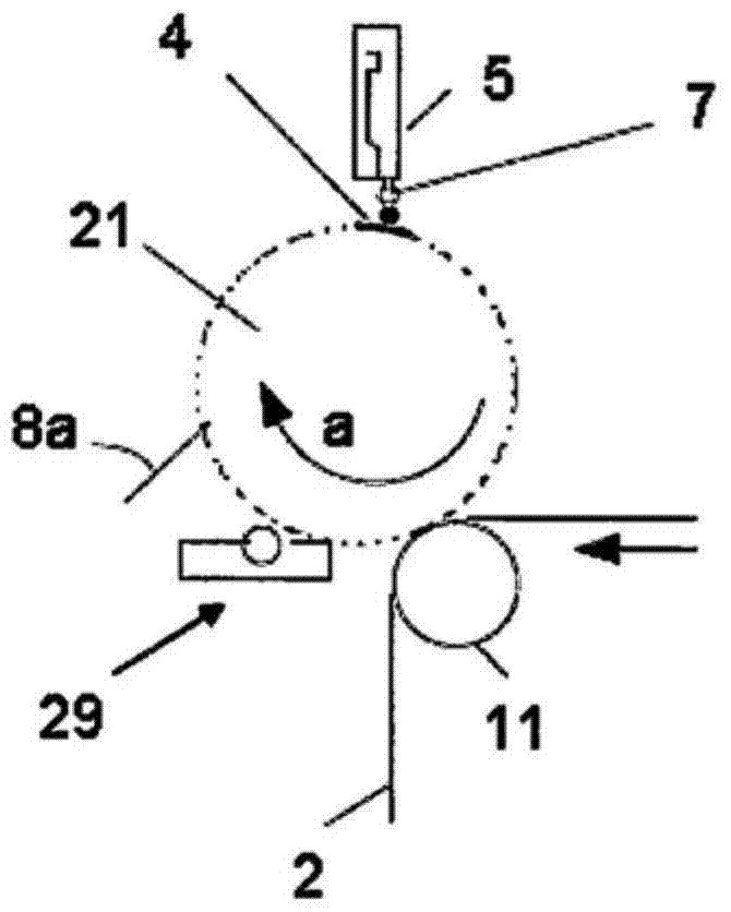
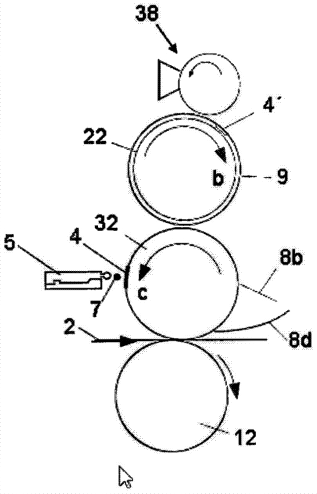
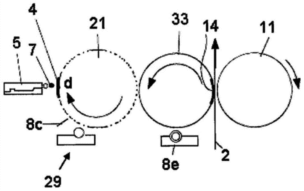
[0032] Such as figure 1 As shown, a first printing press cylinder in the form of an impression cylinder 11 and a second printing press cylinder in the form of an intaglio printing cylinder 21 cooperate in an intaglio printing unit, through which the printing material web 2 passes in a known manner. Between two printing press cylinders. The gravure printing cylinder 21, which rotates in the region of the schematically shown inking unit 29 for inking the cylinder, has on its surface a plurality of pit-shaped depressions, not shown in detail, which are formed during the inking process. The ink unit 29 receives ink therein, which is transferred to the printing material web 2 to produce a first immutable printed image. The intaglio printing cylinder 21 also has on its surface an ink-free circumferential section 4 in which no depressions or wells are formed to receive printing ink in the inking unit 29 . Here, if figure 1 As shown schematically in the figure, when the circumferen...


PUM


Abstract

The method involves applying an additional print image directly on a colorless peripheral section (4) of a gravure printing cylinder (21), a flexo-printing unit-transfer cylinder or gravure printing unit-transfer cylinder by an inkjet printing device (5), where the printing cylinder directly contacts a printed material (2). The print image is transferred from the printing cylinder to the material by the transfer cylinders. The applied print image is removed from the peripheral section by a cleaning device e.g. scraper (8a), during a production print operation of a rotary printing machine. The gravure printing cylinder is provided with a surface made of ceramic. An independent claim is also included for an arrangement for printing a printed material in a rotary printing machine.

Description

technical field [0001] The invention relates to a method and a device for printing a first immutable print image and a second variable print image on a printing material in a rotary printing press. technical background [0002] Shape-constrained or variable printing methods are known from the prior art. Shape-constrained printing methods are, for example, offset, flexographic, gravure or screen printing methods, in contrast to, for example, inkjet and thermal transfer printing, which are referred to as variable methods. [0003] Furthermore, a combined printing method is known, which is also called press-in method or “imprinting” and is based on two successive, shape-constrained and variable individual printing methods. However, the combined printing methods known up to now often have printing-technical problems, in particular that there are often clearly perceptible differences between the printed image of the shape-constrained printing method and the imprinted image of th...

Claims


Application Information

Patent Timeline
Patent Type & Authority Patents(China)
IPC IPC(8): B41F31/08B41M1/04B41M1/06B41M1/10B41F35/04
CPCB41F19/007B41F31/02B41F31/20
Inventor M·施米特-莱文J·克内珀
Owner HEIDELBERGER DRUCKMASCHINEN AG
Learn More