
Filling device capable of quantifying liquid-state fertilizer

A filling device and liquid fertilizer technology, which is applied to liquid materials, mixers with rotating stirring devices, packaging, etc., can solve the problem that the filling speed and filling volume cannot be well adjusted, and it is difficult to observe the amount of injected liquid , production personnel inconvenience and other problems, to achieve the effect of good filling effect, simple structure and high filling efficiency

Inactive Publication Date: 2016-09-28
哈尔滨尼亚农业有限公司
View PDF6 Cites 6 Cited by
  • Summary
  • Abstract
  • Description
  • Claims
  • Application Information

AI Technical Summary

Problems solved by technology

[0002] When filling liquid fertilizers, chemical fertilizer manufacturers often inject liquid medicine directly into the liquid filling equipment, but most of the current filling equipment is not easy to Observe the amount of liquid injected, and when filling, the filling speed and filling volume cannot be well adjusted, which will easily lead to liquid overflow, which not only pollutes the environment, but also causes waste of resources, and some liquids are highly corrosive, so it is not necessary to It is good for cleaning and brings a lot of inconvenience to the production personnel

Method used


Image

  • Filling device capable of quantifying liquid-state fertilizer

Examples


Embodiment 1

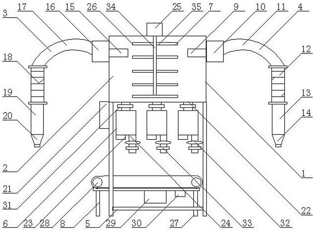
[0021] As shown in the figure, a filling device capable of quantifying liquid fertilizers includes a body 1, a liquid storage tank 2 is installed on the upper end of the body 1, and a first material suction device is installed on the upper ends of the left and right sides of the liquid storage tank 2. 3. The second material suction device 4, the first bracket 5 is installed on the left and right sides of the bottom of the liquid storage tank 2, and three side-by-side dispensing cylinders 6 are installed in the middle of the bottom of the liquid storage tank 2, and the liquid storage tank 2. A mixing device 7 is installed at the middle end of the interior, and a conveying device 8 is installed at the lower end of the dispensing cylinder 6 .

Embodiment 2

[0023] As shown in the figure, the first material suction device 3 is composed of a first liquid inlet pipe 9, a first liquid suction pump 10, a first liquid suction elbow 11, a first telescopic hose 12, and a first liquid suction pipe 13. , the first liquid inlet pipe 9 is installed at the upper left end of the liquid storage tank 2, the first liquid suction pump 10 is installed at the left end of the first liquid inlet pipe 9, and the first liquid suction pump 10 is installed on the left side of the first liquid suction pump 10. The suction elbow 11, the bottom end of the first suction elbow 11 is equipped with a first telescopic hose 12, the bottom end of the first telescopic hose 12 is equipped with a first suction pipe 13, and the first suction pipe 13 The first conical liquid suction nozzle 14 is installed at the bottom end.

Embodiment 3

[0025] As shown in the figure, the second suction device 4 is composed of a second liquid inlet pipe 15, a second liquid suction pump 16, a second liquid suction elbow 17, a second telescopic hose 18, and a second liquid suction pipe 19. , the second liquid inlet pipe 15 is installed at the upper right end of the liquid storage tank 2, the second liquid suction pump 16 is installed at the right end of the second liquid inlet pipe 15, and the second liquid suction pump 16 is installed on the right side of the second liquid inlet pipe. The suction elbow 17, the bottom end of the second suction elbow 17 is equipped with a second telescopic hose 18, the bottom end of the second telescopic hose 18 is equipped with a second suction pipe 19, the second suction pipe 19 second conical liquid suction nozzles 20 of the bottom device.


PUM


Abstract

The invention discloses a filling device capable of quantifying a liquid-state fertilizer. The filling device capable of quantifying the liquid-state fertilizer comprises a machine body, wherein a liquid storage box is installed at the upper end of the machine body; a first material absorption device and a second material absorption device are installed at the upper ends of the left side and the right side of the liquid storage box respectively; a first support is installed at the left side and the right side of the bottom end of the liquid storage box; three parallel sub-packaging barrels are installed at the middle of the bottom end of the liquid storage box; a mixing device is installed at the middle end in the liquid storage box; and a conveying device is installed at the lower ends of the sub-packaging barrels. According to the filling device capable of quantifying the liquid-state fertilizer, which is disclosed by the invention, with the adoption of a quantitative filling manner, the filling device is convenient to fill, controllable in filling amount, low in sub-packaging error, simple and convenient to adjust, high in filling efficiency, and good in filling effect; due to a design of double material absorption devices, the filling device is fast in material absorption speed, and capable of absorbing two different materials simultaneously and mixing the materials, thus meeting a mixed filling need for many materials; and moreover, the filling device is simple to operate, and convenient to use.

Description

technical field [0001] The invention relates to a liquid fertilizer filling device, in particular to a filling device capable of quantifying liquid fertilizer. Background technique [0002] Fertilizer manufacturers often inject liquid medicine directly into liquid filling equipment when filling liquid fertilizers. However, most of the current filling equipment is not easy to observe the amount of injected liquid, and it cannot be well filled when filling. Adjusting the filling speed and filling volume accurately will easily lead to liquid overflow, which not only pollutes the environment, but also causes waste of resources, and some liquids are highly corrosive, which is not conducive to cleaning and brings a lot of inconvenience to production personnel. Contents of the invention [0003] The object of the present invention is to provide a filling device capable of quantifying liquid fertilizer, which adopts the quantitative filling method, which is convenient for filling,...

Claims


Application Information

Patent Timeline
Patent Type & Authority Applications(China)
IPC IPC(8): B65B3/04B65B3/26B65B37/14B01F7/18
CPCB65B3/04B65B3/26B65B37/14B01F27/112B01F27/90
Inventor 黄晓梅孙红瑞吴国会
Owner 哈尔滨尼亚农业有限公司
Learn More