Main beam side-span closure construction method for bond beam cable-stayed bridge

A construction method and side-span technology, applied in bridges, bridge construction, erection/assembly of bridges, etc., can solve the problems of difficult design and construction of three-way consolidation system, difficult to guarantee the quality of concrete construction, complicated construction process, etc. Minimize the interference of external environmental factors, ensure construction quality, and ensure the effect of accurate docking

Active Publication Date: 2016-09-28
CCCC SECOND HARBOR ENG
View PDF5 Cites 6 Cited by
  • Summary
  • Abstract
  • Description
  • Claims
  • Application Information

AI Technical Summary

Benefits of technology

This technology allows for better control over the placement of primary or auxiliary ends during building constructions without affecting their environment's temperature and weather condition. It also simplifies the process of constructing these structures while still allowing them to maintain stability when joined together at different times throughout its lifespan. Additionally, this design makes it easier to manufacture high precision components like those used in bridges.

Problems solved by technology

This patented technical problem addressed in this patents relates to controlling the stability or quality of steel - consistently placed together during casting without causing stress concentration on certain parts like cables. Existing solutions involve either temporarily solidifying ends of the composite beam or integrating them into a single piece called a triplex support frame. However these techniques have limitations when applied over longer periods of time because they require significant labor costs and may result in poorer quality concrete being produced compared to more efficient designs involving multiple forms.

Method used


Image

  • Main beam side-span closure construction method for bond beam cable-stayed bridge
  • Main beam side-span closure construction method for bond beam cable-stayed bridge
  • Main beam side-span closure construction method for bond beam cable-stayed bridge

Examples


Embodiment Construction

[0032] pass below Figure 1 to Figure 8 And the way of enumerating some optional embodiments of the present invention, the technical solution of the present invention (including the preferred technical solution) is described in further detail, and any technical feature and any technical solution in this embodiment do not limit the protection scope of the present invention .

[0033] The main girder side-span closure construction method for the combined girder cable-stayed bridge designed by the present invention comprises the following steps:

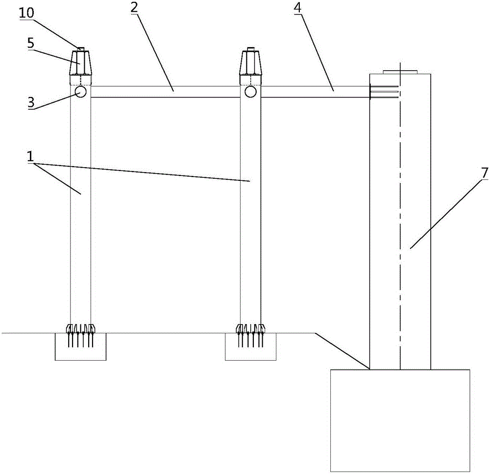
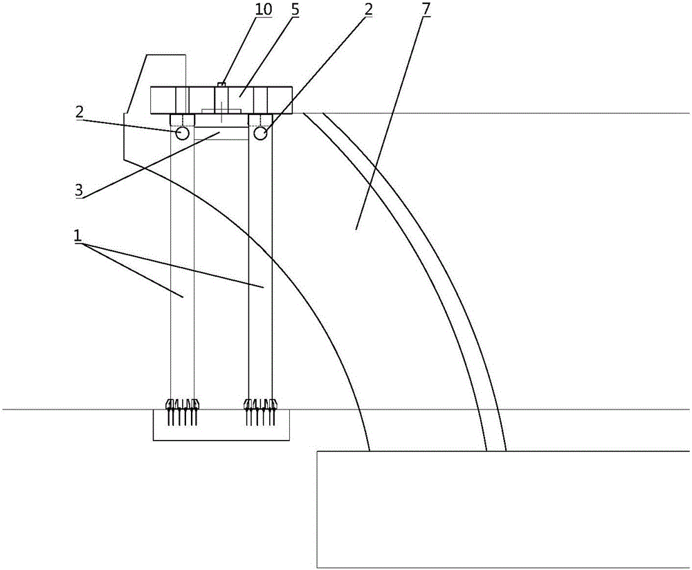
[0034] 1) Set up a support slideway system in the area of ​​the end beam section. The support slideway system includes a steel pipe support device and a slideway device:

[0035] ①Establish the steel pipe support device, the steel pipe support device includes steel pipe column 1, the first parallel joint 2, the second parallel joint 3 and the third parallel joint 4, such as figure 1 and figure 2 As shown: a plurality of vertically a...


PUM


Abstract

The invention discloses a main beam side-span closure construction method for a bond beam cable-stayed bridge. Suspension splicing installation is not conducted on a side-span tail end beam section. A tail-section steel beam is spliced and constructed through a landing steel pipe support. End cross beam reinforced concrete is constructed through a scaffold. A side-span closure opening is additionally formed between the side-span tail end beam section and a sub-tail end beam section. Through reverse pre-deviation of an end cross beam (including a support top board) and jacking reset of the end cross beam, the problem about matching of a bond beam and a standard bond beam section after the end cross beam is poured is effectively solved.

Description


Claims


Application Information

Patent Timeline
Owner CCCC SECOND HARBOR ENG
Why Eureka
Try Eureka