
Flexible suction muffler for compressor

A technology for a silencer and a compressor, applied in the field of compressors, can solve the problem that the compressor cannot adapt to two refrigerator piping systems at the same time, and affects the refrigeration capacity and performance of the compressor, and achieves a simple structure, low cost, and few parts. Effect

Active Publication Date: 2016-09-28
WANBAO GROUP COMPRESSOR CO LTD
View PDF7 Cites 0 Cited by
  • Summary
  • Abstract
  • Description
  • Claims
  • Application Information

AI Technical Summary

Problems solved by technology

That is to say, the suction port of the existing compressor suction muffler is fixed at one position, and correspondingly, the three pipes on the compressor shell are also fixed, one of which is the suction pipe, that is, the compressor suction pipe is fixed, and the exhaust pipe is fixed. It is also fixed, so only one of the same side of the suction and exhaust pipes or the opposite side of the suction and exhaust pipes can be realized.
However, the actual pipeline system of the refrigerator has both the same side and the opposite side of the suction and exhaust pipes, so the same compressor cannot adapt to the two refrigerator pipeline systems at the same time. If the suction pipe and the process pipe are interchanged and assembled to the refrigerator On the system, it seriously affects the cooling capacity and performance of the compressor

Method used


Image

  • Flexible suction muffler for compressor
  • Flexible suction muffler for compressor
  • Flexible suction muffler for compressor

Examples


Embodiment Construction

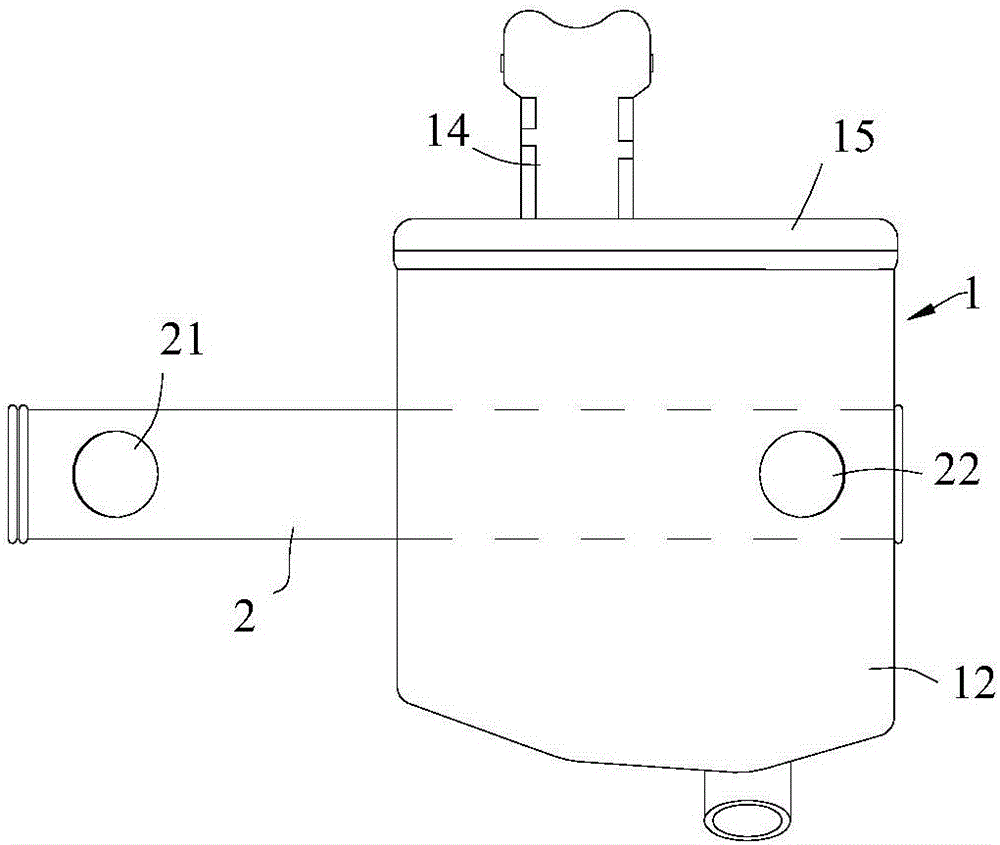
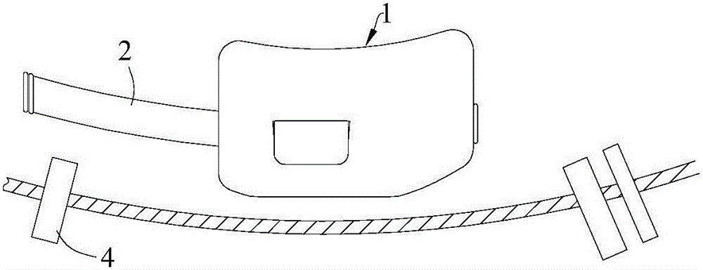
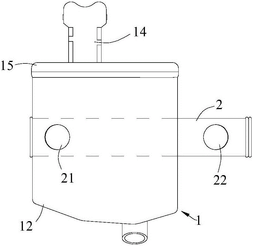
[0025] refer to Figure 1 to Figure 6 , which shows the specific structure of the preferred embodiment of the present invention. The structural characteristics of each element of the present invention will be described in detail below, and if there is a description of the direction (up, down, left, right, front and back), it is based on Figure 5 The shown structure is a reference description, but the actual use direction of the present invention is not limited thereto.

[0026] The present invention provides a compressor flexible suction muffler, comprising a muffler body 1 and an intake pipe 2, the muffler body 1 has a muffler chamber 3 inside, and a left air intake pipe is provided on the left side wall of the muffler body 1 The right air intake pipe hole is provided on the right side wall of the muffler body 1, and the air intake pipe 2 is transversely placed in the left air intake pipe hole and the right air intake pipe hole, and the two ends of the air intake pipe 2 are...


PUM


Abstract

The invention discloses a flexible suction muffler for a compressor. The flexible suction muffler comprises a muffler body and an air intake pipe. A muffling cavity is formed in the muffler body. A left air intake pipe hole is formed in the cavity wall of the left side of the muffler body. A right air intake pipe hole is formed in the cavity wall of the right side of the muffler body. The air intake pipe is arranged in the left air intake pipe hole and the right air intake pipe hole in a penetrating manner. The two ends of the air intake pipe are sealed, a first through hole is formed in the left end of the air intake pipe, and a second through hole is formed in the right end of the air intake pipe. The air intake pipe can be shifted leftwards and rightwards on the muffler body so that the first assembly state and the second assembly state can be formed. According to the first assembly state, the left end of the air intake pipe extends out to the left side of the muffler body, and the first through hole forms a suction opening; and according to the second assembly state, the right end of the air intake pipe extends out to the right side of the muffler body, and the second through hole forms a suction opening. By the adoption of the flexible suction muffler for the compressor, the suction muffler is suitable for two suction pipe arrangement manners of the compressor, multiple functions are achieved, and the number of parts is small; and meanwhile, the suction muffler is suitable for different refrigerator systems, and material preparation and production management are simple.

Description

technical field [0001] The invention is used in the technical field of compressors, and in particular relates to a flexible suction muffler for compressors. Background technique [0002] There are three pipes outside the refrigerator compressor housing, including suction pipe, discharge pipe and process pipe. The arrangement of the three pipes on the compressor is usually one on the left, two on the right, and usually the discharge pipe is on the right. Depending on the internal structure, different compressor platforms can define the left pipe as the suction pipe, or one of the two right pipes as the suction pipe. The internal mechanical structure of the compressor sets the air intake of the suction muffler on the left or right side accordingly, thus ensuring the shortest air intake path and improving the cooling capacity and performance of the compressor. That is to say, the suction port of the existing compressor suction muffler is fixed at one position, and correspondi...

Claims


Application Information

Patent Timeline
IPC IPC(8): F04C29/06
CPCF04C29/06
Inventor 吴丽华谢勇陈忠华吴小凌陈会平李顺刘子杰张建文
Owner WANBAO GROUP COMPRESSOR CO LTD
Learn More