
A compressor test device

A test device, compressor technology, used in mechanical equipment, machine/engine, pump control, etc.

Active Publication Date: 2018-01-30
AECC SHENYANG ENGINE RES INST
View PDF6 Cites 1 Cited by
  • Summary
  • Abstract
  • Description
  • Claims
  • Application Information

AI Technical Summary

Problems solved by technology

[0004] The object of the present invention is to provide a kind of compressor test device, to solve or alleviate at least one problem existing in the background art

Method used


Image

  • A compressor test device
  • A compressor test device

Examples


Embodiment Construction

[0025] To make the objectives, technical solutions, and advantages of the implementation of the present invention clearer, the technical solutions in the embodiments of the present invention will be described in more detail below in conjunction with the accompanying drawings in the embodiments of the present invention. In the drawings, the same or similar reference numerals indicate the same or similar elements or elements with the same or similar functions. The described embodiments are part of the embodiments of the present invention, rather than all of the embodiments. The embodiments described below with reference to the accompanying drawings are exemplary, and are intended to explain the present invention, but should not be construed as limiting the present invention. Based on the embodiments of the present invention, all other embodiments obtained by those of ordinary skill in the art without creative work shall fall within the protection scope of the present invention. ...


PUM


Abstract

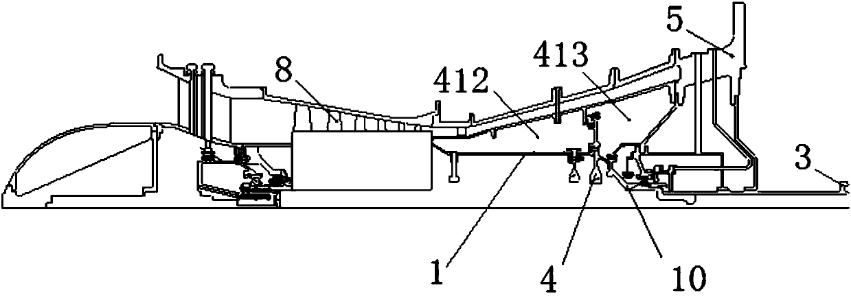
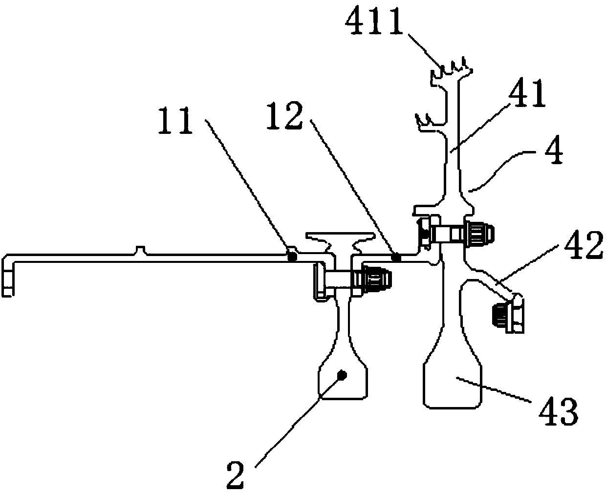
The invention discloses a compressor test device and relates to the technical field of engines. The compressor test device comprises a compressor, a case and a rotor driving shaft sleeve, and further comprises a drum shaft, a sealing disc and a driving shaft, wherein the sealing disc comprises a sealing cavity division part and a connecting part; labyrinth seals are arranged on the outer circumference of the sealing cavity division part and sealed with the inner chamber of the case; one end of the drum shaft is connected with the sealing cavity division part, and the other end of the drum shaft is connected with an outlet sealing disc of the compressor; the connecting part of the sealing disc is fixedly connected with one end of the rotor driving shaft sleeve, and the other end of the rotor driving shaft sleeve is connected with the driving shaft; and the sealing cavity division part divides a sealing cavity into a balance disc front cavity and a balance disc rear cavity. The compressor test device has the following beneficial effects: the sealing cavity division part divides the sealing cavity into the balance disc front cavity and the balance disc rear cavity, and the axial force born by the whole rotor system can be adjusted by controlling the pressure difference between the two cavities.

Description

Technical field [0001] The invention relates to the technical field of engines, in particular to a compressor test device. Background technique [0002] As one of the core components of the engine, the compressor is required to have a high boost ratio and high efficiency so that the engine can obtain higher thermal efficiency and unit power. In addition, a higher surge margin is required to adapt to the frequent maneuvering of the aircraft. For general-purpose core machines, versatility requirements must also be considered. Since the air flow in the compressor is a full three-dimensional, viscous, unsteady flow, its flow law is quite complicated. So far, people’s understanding of the gas flow mechanism in the turbomachine is still under continuous development and improvement. Since the years, computational fluid dynamics has made significant progress. In terms of turbomachinery, it has developed from two-dimensional inviscid analysis to full three-dimensional viscous flow analys...

Claims


Application Information

Patent Timeline
Patent Type & Authority Patents(China)
IPC IPC(8): F04D27/00
CPCF04D27/001
Inventor 张新强王华印雪梅刘冬
Owner AECC SHENYANG ENGINE RES INST
Learn More