Meter and device for acquiring meter data

A technology of meter data and collection device, applied in the field of wireless meter reading, can solve problems such as unable to complete meter reading in time, and achieve the effects of clear shooting results, shortened meter reading cycle, and clear shooting results

Active Publication Date: 2016-09-28
ENN GRP CO LTD
View PDF4 Cites 6 Cited by
  • Summary
  • Abstract
  • Description
  • Claims
  • Application Information

AI Technical Summary

Problems solved by technology

[0003] In order to solve the problem that meter readers cannot complete meter reading in time due to the influence of various factors in real life, the invention provides a meter data collection device, including a camera and a communication module. The camera is fixed on the meter. And the framing direction of the camera is facing the instrument display area, and the camera is used to take pictures or videotape the display results of the instrument display area on a regular basis; the camera is electrically connected to the communication module, and the communication module is used to connect the camera The captured image or video is wirelessly transmitted to the background server to represent the data with a centralized reader

Method used


Image

  • Meter and device for acquiring meter data
  • Meter and device for acquiring meter data
  • Meter and device for acquiring meter data

Examples


Embodiment 1

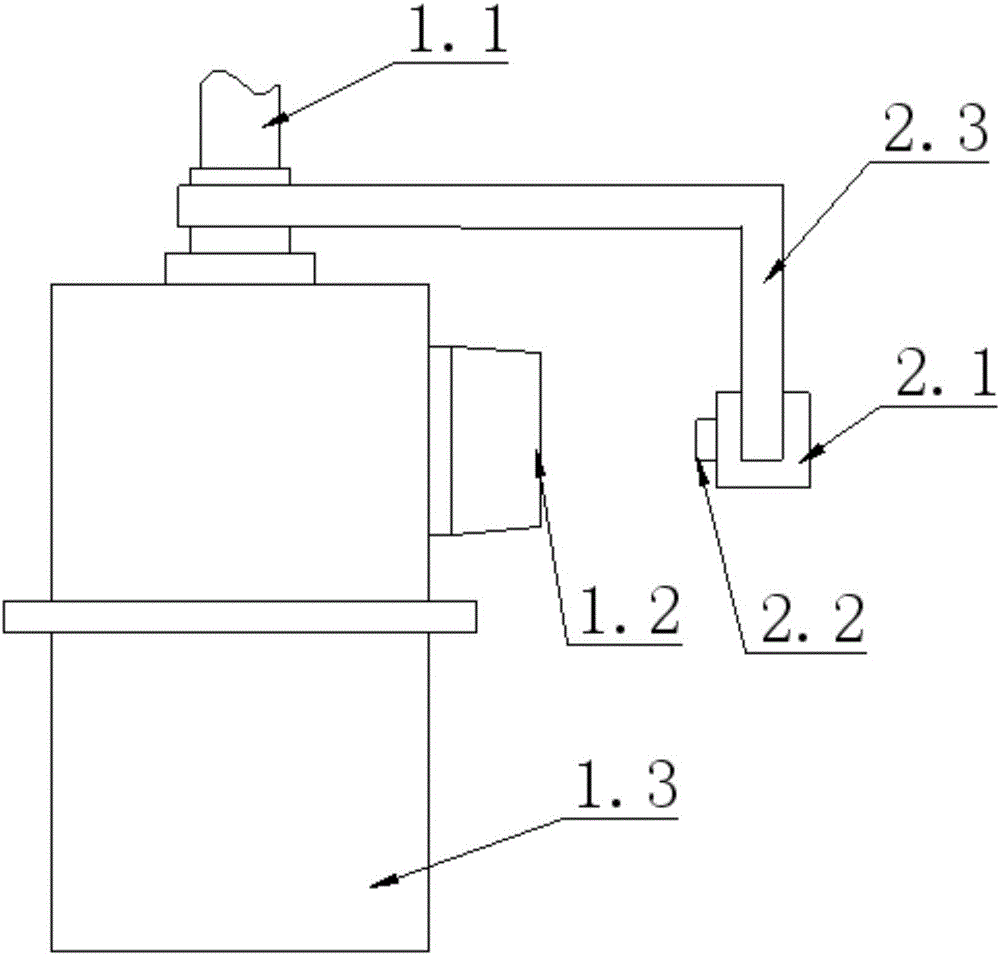
[0039] The pipeline 1.1 in this embodiment is connected with a nut for limiting the displacement of the bracket 2.3 in the axial direction of the pipeline 1.1. A pin for the nut to rotate, a pin for limiting the rotation of the bracket 2.3 is pierced between the bracket 2.3 and the housing of the instrument 1.3, and the pins are all locked by the lock to prevent the pin from being taken out. That is, there are threads on the outer wall of the pipeline 1.1, and the nuts are tightened on the outer wall of the pipeline 1.3; the end of the bracket 2.3 is clamped between the nut and the shell of the meter 1.3. For the convenience of installation, the shell of the meter 1.3 can be located at the installation place of the pipe 1.1 A support table is set, and the end of the support 2.3 is clamped and fixed by the support table and nuts, so as to realize the axial limit of the support 2.3.

[0040] When the pin is inserted between the nut and the outer wall of the pipe 1.1, the radially ...

Embodiment 2

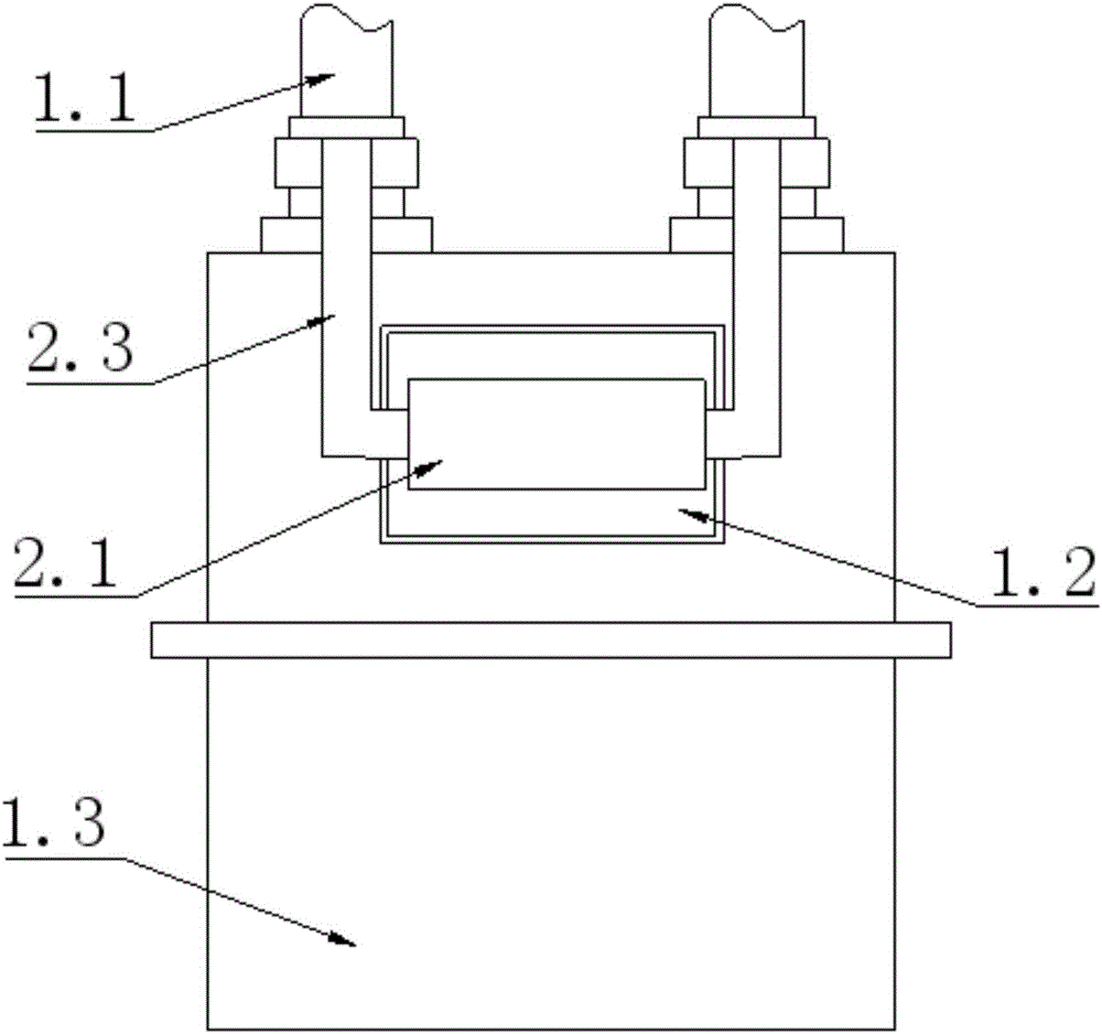
[0045] This embodiment is another embodiment of the first embodiment. On the basis of the first embodiment, when the pin is inserted between the nut and the shell of the meter 1.3 (or the support platform on the shell of the meter 1.3), the nut The pins extending parallel to the axial direction of the pipe 1.1 are pierced between the shell of the instrument 1.3 to prevent the nut from rotating and loosening and to ensure the stability of the axial limit; a counterbore is set on the outer wall of the pipe 1.1, along the direction of the nut. Open a through hole on the nut in the axial direction, and then open a small hole in the corresponding place on the shell of the instrument 1.3. The pin passes through the nut and penetrates into the small hole on the shell of the instrument 1.3. position, prevent the nut from rotating, and realize the axial limit.

[0046] Limit the bracket 2.3 from two directions to prevent relative displacement between it and the meter 1.3, and ensure th...

Embodiment 3

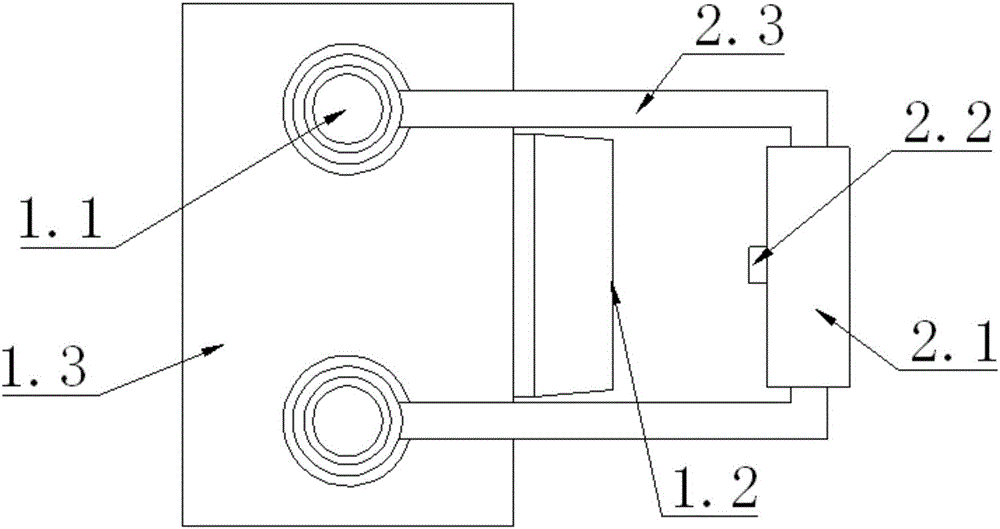
[0050] This is an example. There are pins between the bracket 2.3 and the outer wall of the pipeline 1.1 to limit the rotation of the bracket 2.3 and the displacement along the axial direction of the pipeline 1.1. The pins are all locked by the lock to prevent the pins from being taken out. That is, between the bracket 2.3 and the outer wall of the pipeline 1.1, a pin extending in the radial direction is shot, and the pin passes through the rear end of the bracket 2.3 and penetrates into the counterbore on the outer wall of the pipeline 1.1, and the bracket 2.3 is in the axial and circumferential directions. No displacement can be generated; limit the bracket 2.3 from two directions to prevent relative displacement between it and the meter 1.3, and ensure that the result captured by the camera 2.2 is the display result of the corresponding meter 1.3, not other meters 1.3 display results.

[0051] At the same time, in order to prevent the pin from being taken out and cause the ...


PUM


Abstract

The invention discloses a meter and a device for acquiring meter data. The device for acquiring the meter data comprises a camera and a communication module, wherein the camera is fixed on the meter; the viewing direction of the camera is just opposite to a meter display area; the camera is used for photographing or shooting a display result of the meter display area; the camera is electrically connected with the communication module; the communication module is used for wirelessly transmitting an image or a video shot by the camera to a background server so as to read display numbers of the meters intensively. The device is mounted on an existing meter; the camera and a communication device are disposed, the camera shoots the content of the meter display area, the communication device sends a shot result to the background server for checking by operating staff; the operating staff can read the display numbers of the meters at different positions without visiting users, thus a lot of human costs are saved, the meter reading period is greatly shortened, new bills are convenient to generate in time and are provided for the users to pay.

Description

technical field [0001] The invention relates to the technical field of wireless meter reading, in particular to a meter data acquisition device and a meter. Background technique [0002] In daily life, common energy meters are mainly ordinary meters and IC card meters. The difference between ordinary meters and IC card meters lies in the payment method: IC card meters are prepaid, that is, a certain The prepaid amount, and then write the card information into the table, within the limit of the prepaid amount, the user can use it arbitrarily. The general meter is post-paid, that is, after the user consumes, the meter reader regularly checks the display value of the general meter corresponding to each user, which is called meter reading; after the meter is read, compare the last payment record to generate a new bill . There is an indispensable link in the payment of general meters, which is door-to-door meter reading, which requires multiple meter readers to read each house ...

Claims


Application Information

Patent Timeline
Patent Type & Authority Applications(China)
IPC IPC(8): H04N7/18H04N5/235H04N5/225G03B17/56G03B30/00
CPCH04N7/18G03B17/56H04N23/50H04N23/74
Inventor 符子建孙磊董胜龙高京苏金柱
Owner ENN GRP CO LTD
Why Eureka
Try Eureka