Supercharge Your Innovation With Domain-Expert AI Agents!

Axis deviation detection device for beam sensor

A technology for detecting device and axis offset, which is applied in the direction of measuring device, instrument, and re-radiation, and can solve the problems of axis offset detection of difficult laser beam sensors, etc.

Active Publication Date: 2016-09-28
DENSO CORP
View PDF11 Cites 5 Cited by
  • Summary
  • Abstract
  • Description
  • Claims
  • Application Information

AI Technical Summary

Problems solved by technology

Therefore, in this technology, it is difficult to detect the axis deviation of the laser beam sensor while the vehicle is running

Method used


Image

  • Axis deviation detection device for beam sensor
  • Axis deviation detection device for beam sensor
  • Axis deviation detection device for beam sensor

Examples


Embodiment Construction

[0042] The following embodiments of the present disclosure and appended Figure 1 to explain.

[0043] First, a first embodiment of the present disclosure will be described.

[0044] [1. Explanation of the structure of the driving assistance system 1]

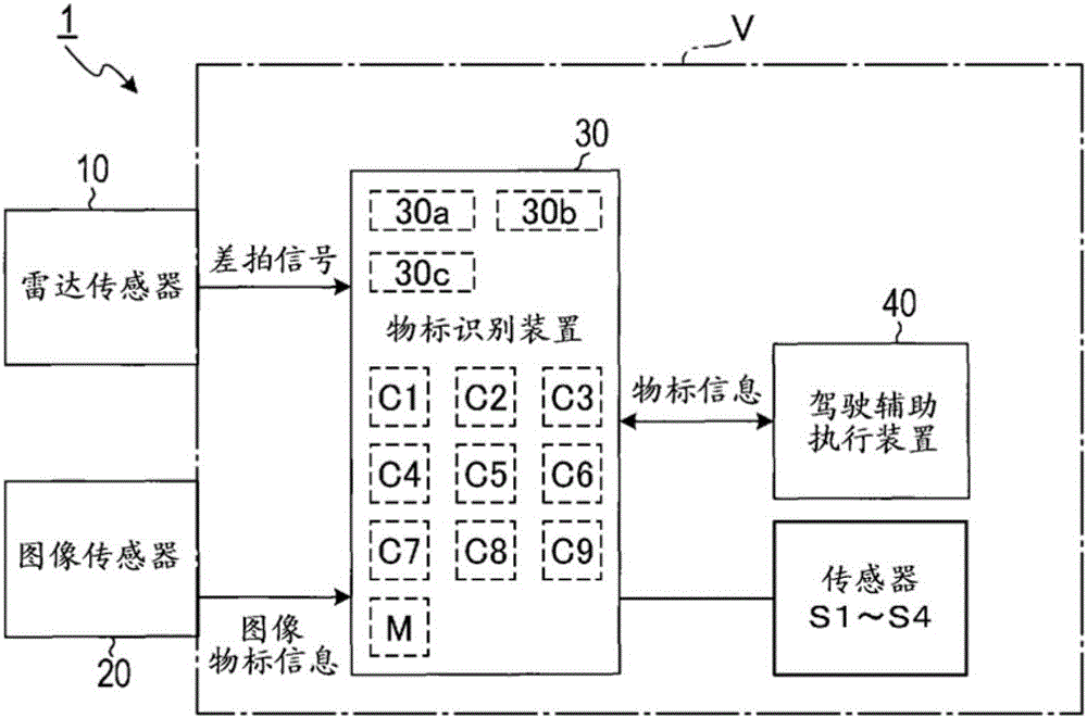
[0045] The driving assistance system 1 according to the first embodiment is composed of a radar sensor 10 , an image sensor 20 , an object marker recognition device 30 , and a driving assistance execution device 40 , and is mounted on a vehicle V. As shown in FIG.

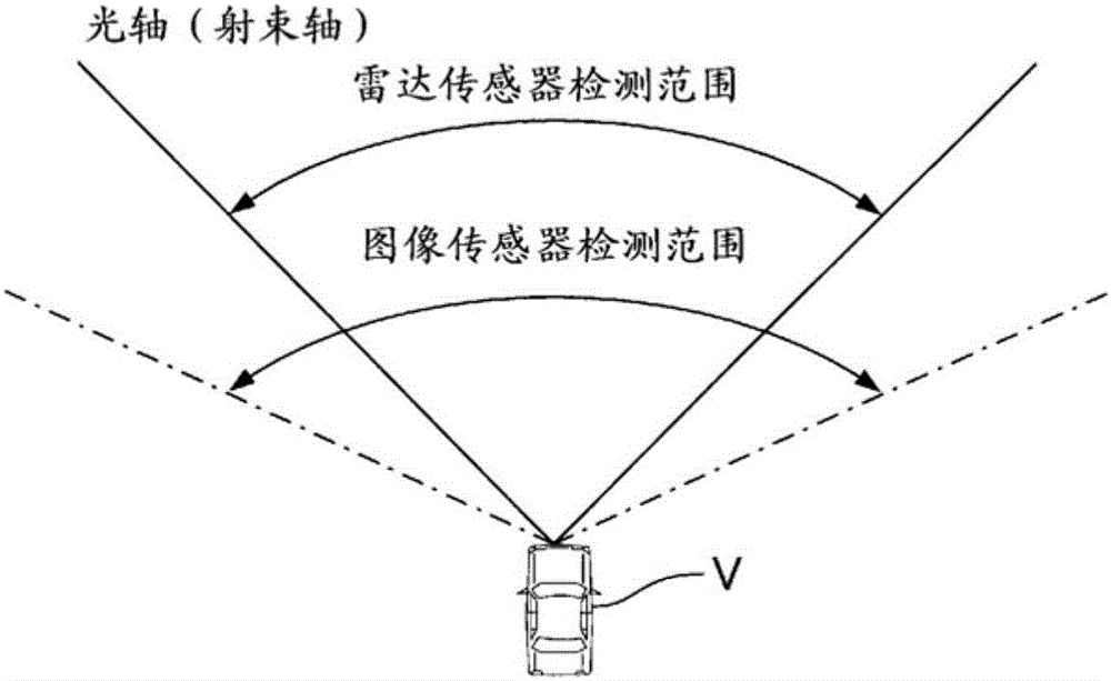
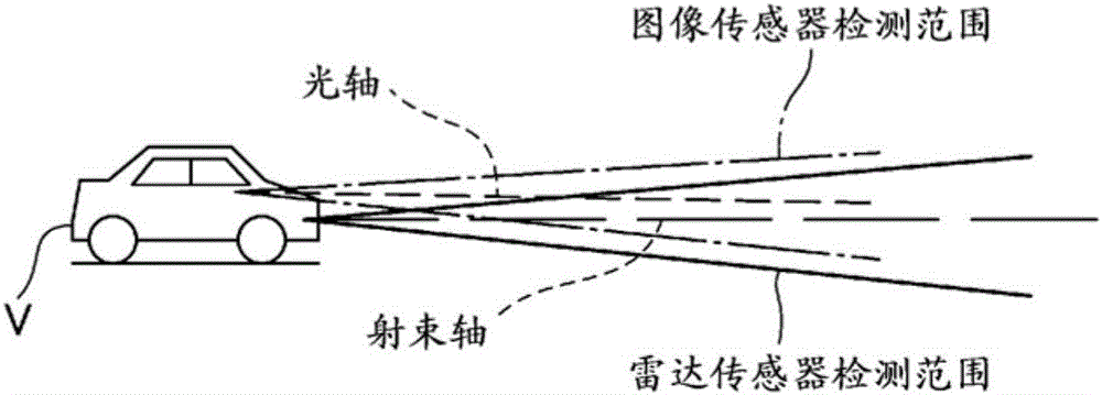
[0046]The object marker recognition device 30 is connected so as to be able to communicate with each of the radar sensor 10 , the image sensor 20 , and the driving assistance execution device 40 . The radar sensor 10 irradiates radar waves (radar beams) toward a first detection area (first detection range) set in front of the host vehicle, and receives the reflected waves (reflection beams). In addition, the image sensor 20 images a second detection area set in f...


PUM


Abstract

On the basis of the result of first target recognition processing by a beam recognition unit and the result of second target recognition processing by an image recognition unit, an axis deviation detection device for a beam sensor calculates the proportion of the number of times at least one preceding vehicle traveling in front of a vehicle was recognized in both the first target recognition processing and the second target recognition processing to the number of times the at least one preceding vehicle was recognized in at least image recognition processing, and according to the value of the calculated proportion, detects an axis deviation from a designed beam axis position of a beam axis of the beam sensor in a vertical plane including the beam axis.

Description

technical field [0001] The present disclosure relates to a technique for detecting axial misalignment of a beam sensor mounted on a vehicle. Incidentally, the axis misalignment of the beam sensor refers to a case where a reference axis (hereinafter, referred to as a beam axis) along a traveling direction of a beam output from the beam sensor is displaced from a previously designed axis position. Background technique [0002] Conventionally, beam sensors have been used to perform various controls to improve the driving safety of vehicles. The beam sensor emits detection beams such as laser light, ultrasonic waves, and millimeter waves, and detects reflected beams, thereby detecting objects existing around the vehicle. [0003] The beam sensor is mounted at a predetermined mounting position of the vehicle so as to irradiate a probe beam to a predetermined irradiation range, and the beam axis coincides with a predetermined axis position. Therefore, if the installation positio...

Claims


Application Information

Patent Timeline
Patent Type & Authority Applications(China)
IPC IPC(8): G01S7/40G01S13/34G01S13/86G01S13/93G01S13/931
CPCG01S13/86G01S13/931G01S13/867G01S2013/9324G01S2013/9323G01S2013/93271G01S7/4034G01S7/4026
Inventor 高木亮
Owner DENSO CORP
Features
  • R&D
  • Intellectual Property
  • Life Sciences
  • Materials
  • Tech Scout
  • Unparalleled Data Quality
  • Higher Quality Content
  • 60% Fewer Hallucinations
Learn More