

Plant lighting apparatus
A lighting equipment and plant technology, applied in botany equipment and methods, lighting and heating equipment, mechanical equipment, etc., can solve the problems of weak plant growth, reduced harvest quality, uneven light intensity, etc., and achieve the effect of improving quality
- Summary
- Abstract
- Description
- Claims
- Application Information
AI Technical Summary
Problems solved by technology
Method used
Image

Examples
no. 1 example
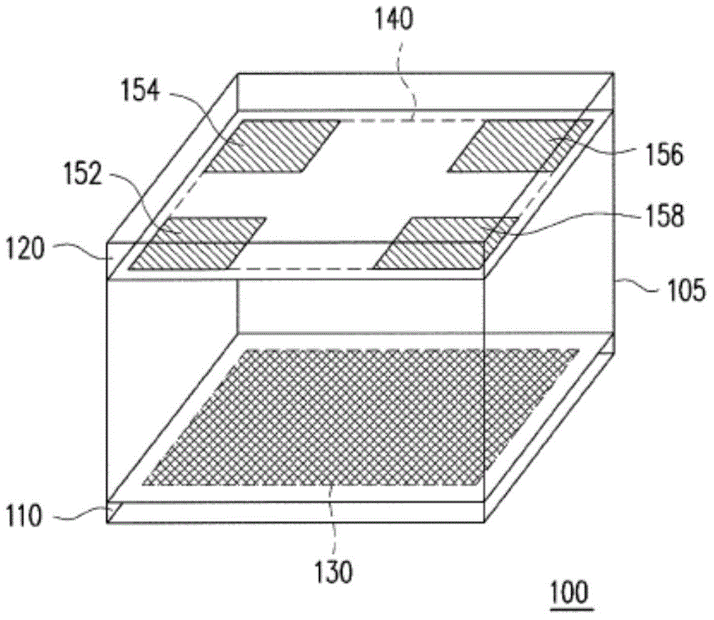
[0056] figure 1 It is a schematic block diagram of the plant lighting device 100 according to the first embodiment of the present invention. Please refer to figure 1. The plant lighting device 100 may include a main body 105 , a planting area 130 , and a light emitting area 140 . In this embodiment, the body 105 may be a square box, and has a bottom surface (also called a first surface) 110 and a top surface (also called a second surface) 120 . The first surface and the second surface are set oppositely. For example, the first surface and the second surface are parallel to each other. There is a certain distance between the bottom surface (first surface) 110 and the top surface (second surface) 120, so that the plants growing in the planting area 130 can have a more suitable growth space, and can obtain sufficient illumination. In an embodiment of the present invention, the distance between the bottom surface (first surface) 110 and the top surface (second surface) 120 m...
no. 2 example
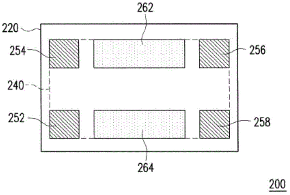
[0061] figure 2 It is a schematic block diagram of the light source configuration of the plant illumination device 200 according to the second embodiment of the present invention. Please refer to figure 2 . To simplify the description, figure 2 The main body, bottom surface (first surface), and planting area of the plant lighting device 200 are omitted, and the top surface (second surface) 220 and the light emitting area 240 of the plant lighting device 200 are mainly shown. Specifically, in this embodiment, the light emitting area 240 is, for example, rectangular and includes two long sides and two short sides. In particular, in order to allow the light source on the light emitting area 240 to evenly irradiate the light on the planting area 130, in addition to the main light source group 70 in the embodiment of the present invention, at least one group of secondary light sources can also be provided in other parts of the main body 105 light source group. The seconda...
no. 3 example
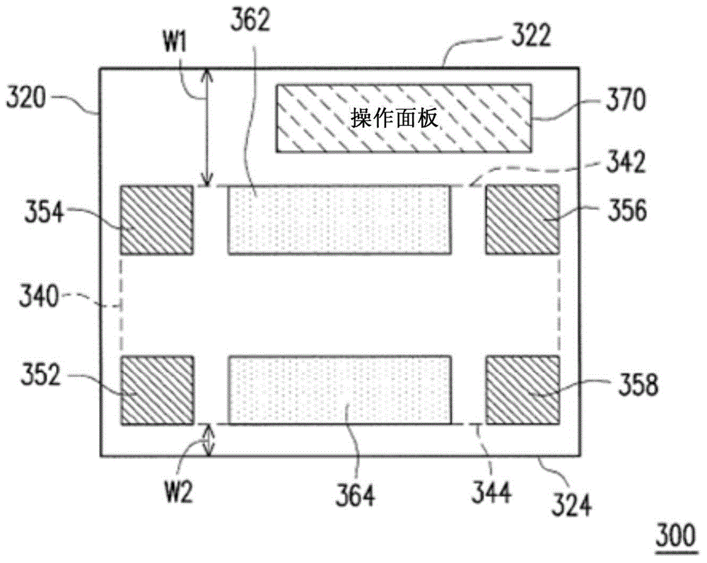
[0063] image 3 It is a schematic block diagram of the light source configuration of the plant illumination device 300 according to the third embodiment of the present invention. Please refer to image 3 . To simplify the description, image 3 The main body, bottom surface (first surface), and planting area of the plant lighting device 300 are omitted, and the top surface (second surface) 320 and the light emitting area 340 of the plant lighting device 300 are mainly shown. In this embodiment, the top surface (second surface) 320 includes a light emitting area 340 and an operation panel 370 . The operation panel 370 is used to control the plant lighting device 300, and may have a control circuit, such as controlling the current supply of the plant lighting device 300, setting the lighting time, and the like. The operation panel 370 can be arranged on one side of the body, one side of the planting area, or one side of the top surface (second surface) 320 , and the present...
PUM
 Abstract
Description
Claims
Application Information