In-mold forming method and in-mold forming equipment
What is AI technical title?
AI technical title is built by Patsnap AI team. It summarizes the technical point description of the patent document.
A technology of in-mold molding and equipment, applied in the field of electronics, can solve problems such as large stress and deformation
Active Publication Date: 2018-10-12
LENOVO (BEIJING) LTD
View PDF4 Cites 0 Cited by
Summary
Abstract
Description
Claims
Application Information
AI Technical Summary
This helps you quickly interpret patents by identifying the three key elements:
Problems solved by technology
Method used
Benefits of technology
Problems solved by technology
[0007] Further, due to the existence of the above technical problems, in the prior art, when an equipment component is composed of plastic parts, carbon fiber sheets or metal parts, there will be technical problems of deformation due to large stress
Method used
Image
Click on the blue label to locate the original text in one second.
Reading with bidirectional positioning of images and text.
Examples
Embodiment 1
[0051] During the production process of the first in-mold molding equipment, a large stress will be generated between plastic parts, carbon fiber sheets or metal parts.
[0052] In order to reduce the stress generated between plastic parts, carbon fiber sheets or metal parts during in-mold molding. An embodiment of the present invention provides an in-mold forming method of an in-mold forming device that can be used to manufacture an electronic device casing.
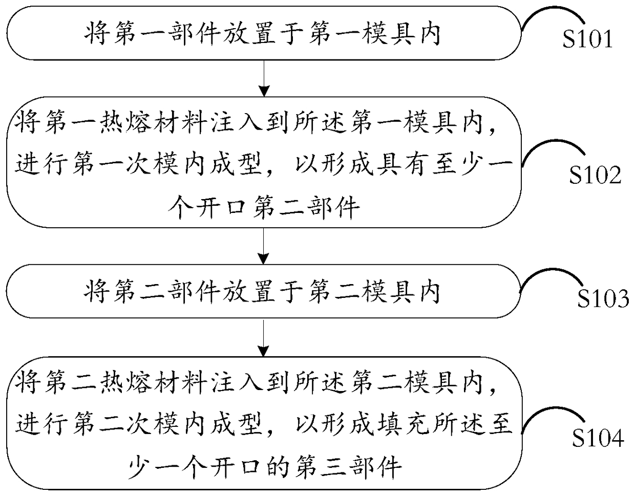
[0053] Please refer to figure 1 , the embodiment of the present application provides an in-mold forming method for forming the first in-mold forming device, the method comprising:
[0054] S101: placing the first part in the first mold;
[0055] S102: inject a first hot melt material into the first mold, and perform a first in-mold molding to form a second part with at least one opening;
[0056] S103: placing the second component in a second mold;
[0057] S104: Inject a second hot melt material into the second mol...
Embodiment 2
[0083]Based on the same inventive concept, an in-mold forming device is also provided in the embodiment of the present invention, please refer to Figure 4 The in-mold forming equipment provided by the embodiment of the present invention includes: a first component 41, a first in-mold forming component 42, and a second in-mold forming component 43, wherein,
[0084] The first in-mold component 42 forms a second part together with the first part 41 by a first in-mold, and the second part includes at least one opening;
[0085] Said second in-molding component 43 forms a third part together with said second part by a second in-molding, said third part comprising a portion filling said at least one opening.
[0086] Specifically, the first component 41 is a component formed by stamping a carbon fiber plate or a metal plate.
[0087] The thickness of the first component 41 is 0.05mm˜2.0mm.
[0088] The first upper surface of the first in-mold forming component 42 and the second ...
PUM
Property
Measurement
Unit
flexural modulus
aaaaa
aaaaa
thickness
aaaaa
aaaaa
fatigue bending times
aaaaa
aaaaa
Abstract
The invention discloses an intra-die forming method and intra-die forming equipment. The method comprises the following steps: putting a first component into a first die; pouring a first hot melting material into the first die to carry out first time of intra-die forming, so as to form a second component with at least one opening; putting the second component into a second die; and pouring a second hot melting material into the second die to carry out second time of intra-die forming, so as to form a third component for filling up the at least one opening, wherein the third component is the first intra-die forming equipment. The method disclosed by the invention is used for solving the technical problem of a one-time intra-die forming technology that relative great stress is generated between plastic components, carbon fiber plates or metal parts in the prior art, thus achieving the technical effect of reducing the stress between the plastic components, the carbon fiber plates or the metal parts during intra-die forming.
Description
technical field [0001] The invention relates to the field of electronic technology, in particular to an in-mold forming method and an in-mold forming device. Background technique [0002] At present, most electronic devices use carbon fiber sheet, stainless steel, some Alcoa, etc. as the materials for the shell, so as to reduce the thickness and weight of the electronic device, and at the same time improve the protection strength of the shell for the electronic device. [0003] In the prior art, carbon fiber sheets, stainless steel, and some Alcoa frames are combined with plastic in a mold to form a complete structural part. [0004] In the process of implementing the technical solutions in the embodiments of the present application, the inventors of the present application found that the prior art has at least the following technical problems: [0005] In the prior art, during the one-time molding process of putting the carbon fiber sheet and metal parts into the mold, sin...
Claims
Application Information
Patent Timeline
Application Date:The date an application was filed.
Publication Date:The date a patent or application was officially published.
First Publication Date:The earliest publication date of a patent with the same application number.
Issue Date:Publication date of the patent grant document.
PCT Entry Date:The Entry date of PCT National Phase.
Estimated Expiry Date:The statutory expiry date of a patent right according to the Patent Law, and it is the longest term of protection that the patent right can achieve without the termination of the patent right due to other reasons(Term extension factor has been taken into account ).
Invalid Date:Actual expiry date is based on effective date or publication date of legal transaction data of invalid patent.

