Liquid level detection device and method
A technology of liquid level detection and detection holes, which is applied in the direction of buoy liquid level indicators, etc., to achieve the effects of stable performance, convenient liquid level detection operation, and simple structure
- Summary
- Abstract
- Description
- Claims
- Application Information
AI Technical Summary
Problems solved by technology
Method used
Image

Examples
Embodiment Construction
[0028] In order to help those skilled in the art to accurately understand the claimed subject matter of the present invention, specific implementations of the present invention will be described in detail below in conjunction with the accompanying drawings.
[0029] Spatial positional terms or spatial relational terms, such as "vertical", "longitudinal", etc., are used herein for convenience of description to describe the relationship of one element or feature to another element or feature as illustrated in the figures . It will be appreciated that the spatially relative terms are intended to encompass different directional orientations of the device, component, or structure in use or operation in addition to the orientation depicted in the figures. In this article, "vertical" and "longitudinal" refer to the directions shown in the drawings, and also the direction along the liquid level.
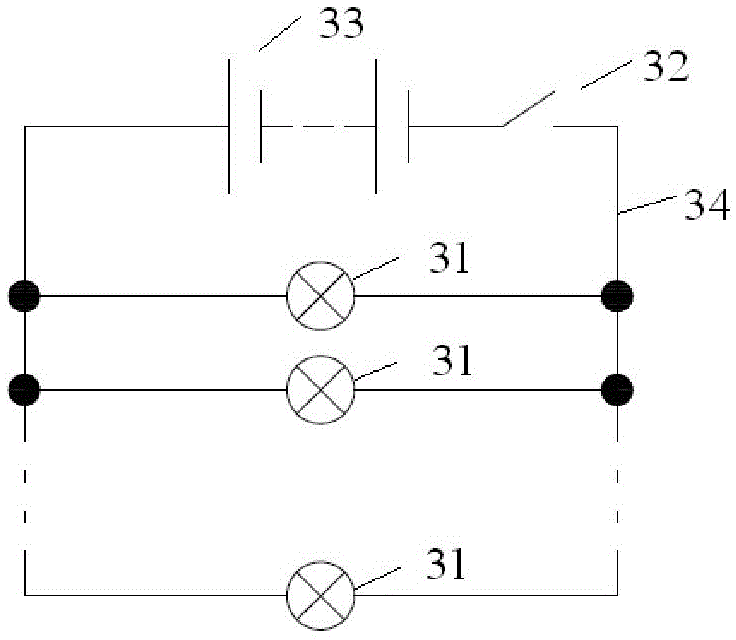
[0030] see figure 1 , is a schematic diagram of the liquid level detection device invo...
PUM
 Abstract
Description
Claims
Application Information
PatSnap Eureka turns technology decisions into work you can execute. Powered by our Innovation Knowledge Graph, it runs expert workflows across engineering, life sciences, materials and intellectual property. Get your review-ready output in minutes.


