Support of light emitting diode and preparation method

A technology for light-emitting diodes and a manufacturing method, which is applied in the manufacture of semiconductor/solid-state devices, electrical components, and electrical solid-state devices, etc., can solve the problems of poor thermal conductivity, too many molds, and high costs, so as to reduce production costs, simplify manufacturing processes, and improve The effect of suitability

Active Publication Date: 2005-11-16
深圳可瑞高新材料股份有限公司
View PDF0 Cites 6 Cited by
  • Summary
  • Abstract
  • Description
  • Claims
  • Application Information

AI Technical Summary

Problems solved by technology

However, this kind of bracket has the following disadvantages: too many molds are used, the investment is large, the precision of the packaging fixture is high, and the subsequent finished product must be molded before it can be used, resulting in troublesome use
However, this kind of bracket has the following disadvantages: 1) Since the edge of the metal plate is a conductor, it is difficult to make side electrodes, so jumpers must b

Method used


Image

  • Support of light emitting diode and preparation method
  • Support of light emitting diode and preparation method
  • Support of light emitting diode and preparation method

Examples


Example Embodiment

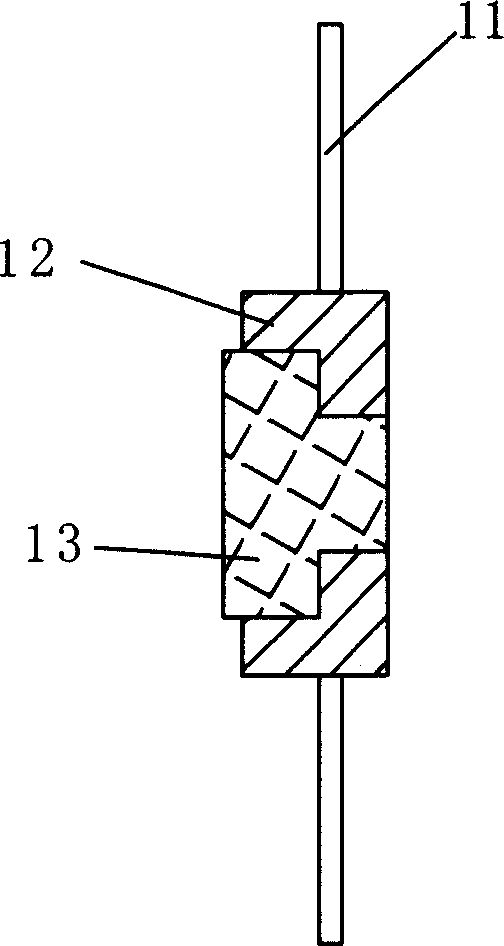
[0027] see Figure 7 to Figure 10 , the manufacturing method of a kind of light-emitting diode support of the present invention comprises following process: 1) make the circuit board 4 with electrode by the organic resin-based metal-clad plate through printed circuit board process; 2) make through-hole 43 on the circuit board 4 ; 3) Fix the copper piece 6 in the said through hole 43 . After the support is formed, the chip can be fixed on the copper piece. In step 1), the electrodes 5 are made by the printed circuit board process on the surfaces of both ends of the circuit board. In this embodiment, the electrodes are formed by etching on the circuit board through the existing printed circuit board process; Electrodes 5 are formed on the top surface 411, the bottom surface 413 of the end portion and the side surface 412 connecting the top and bottom surfaces.

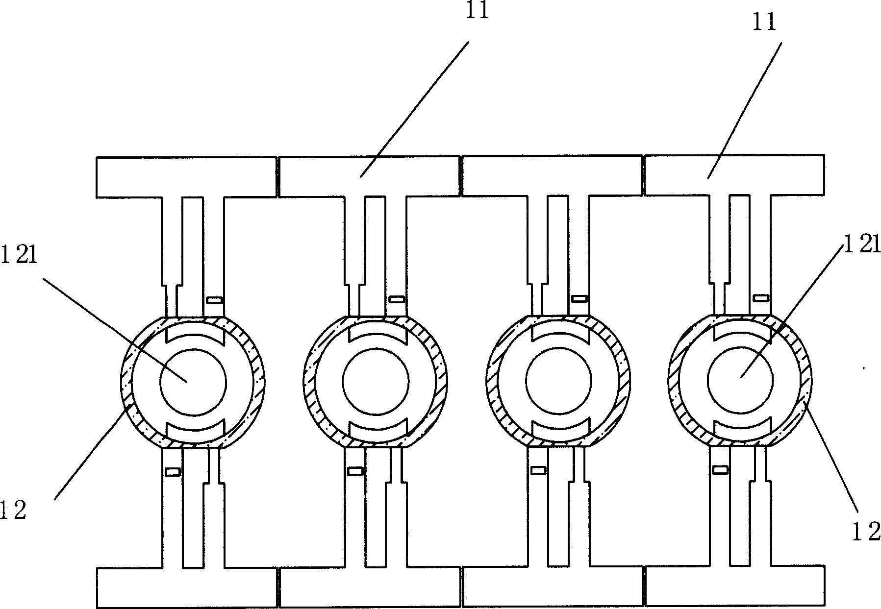
[0028] see Figure 7 to Figure 9 , during mass production, several light-emitting diode brackets can be made on a c...


PUM


Abstract

The method includes following steps: (1) circuit board with electrodes is fabricated from organic resin covered metal foil plate through printing circuit technique; (2) making through hole on circuit board; (3) fixing copper piece inside the through hole. The bracket of light emitting diode includes copper piece, circuit board, as well as positive and negative electrodes. Both positive electrode and negative electrode includes face electrode, bottom electrode, and side electrode, which are printed on top, side and bottom surface at end part of the circuit board. The side electrode is connected to the face electrode and bottom electrode. Based on need, circuit board and copper piece in different shapes are easy to be prepared. Thus, outline of bracket is easy to be changed so as to provide good adaptability for subsequent handling, reduce dependability on die set.

Description

【Technical field】 [0001] The invention relates to the field of high-power light-emitting diodes, in particular to a support for high-power light-emitting diodes. 【Background technique】 [0002] The light-emitting diode (also known as LED) bracket is the carrier of the semiconductor light-emitting chip. It undertakes the functions of fixing the chip, connecting the chip with the external circuit, and conducting the heat generated when the chip is working. [0003] figure 1 and figure 2 Disclosed is the first structure of the existing light-emitting diode bracket, which is a composite type of plastic and copper parts. The light-emitting diode bracket includes an electrode 11, a colloid 12 and a copper piece 13. The electrode 11 is located on both sides of the colloid 12 and is integrally injection-molded with the colloid 12. The center of the colloid 12 is provided with a through hole 121, and the copper piece 13 is installed in the through hole. Within 121. The manufactu...

Claims


Application Information

Patent Timeline
IPC IPC(8): H01L33/00
Inventor 李锋
Owner 深圳可瑞高新材料股份有限公司
Why Eureka
Try Eureka