Supercharge Your Innovation With Domain-Expert AI Agents!

Power System Protection Circuit

A technology for protecting circuits and power systems, applied to electrical components, output power conversion devices, etc., can solve problems such as inability to protect chip power supplies, and achieve the effect of avoiding loop instability and loop oscillation

Active Publication Date: 2019-07-12
SHANGHAI EASTSOFT MICROELECTRONICS
View PDF4 Cites 0 Cited by
  • Summary
  • Abstract
  • Description
  • Claims
  • Application Information

AI Technical Summary

Problems solved by technology

[0008] However, the existing chip protection circuit using the peak current detection method still cannot effectively protect the chip and the power supply in some cases.

Method used


Image

  • Power System Protection Circuit
  • Power System Protection Circuit
  • Power System Protection Circuit

Examples


Embodiment Construction

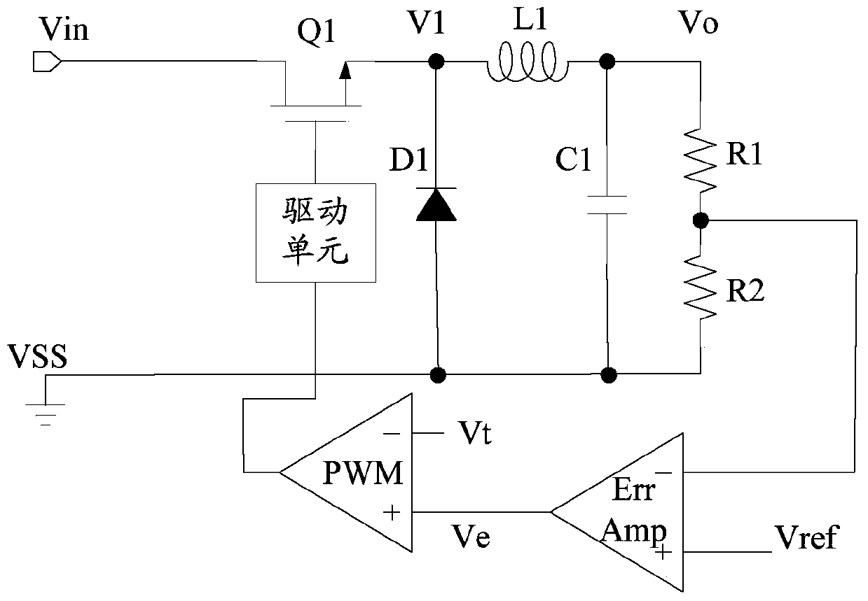
[0028] In the existing chip protection circuit, the input peak current is detected at the input end of the circuit, and the output peak current is limited at the output end of the circuit, so as to realize the protection of the power tube. However, the existing chip protection circuit adopting the peak current detection method still cannot effectively protect the chip and the power supply in some cases.

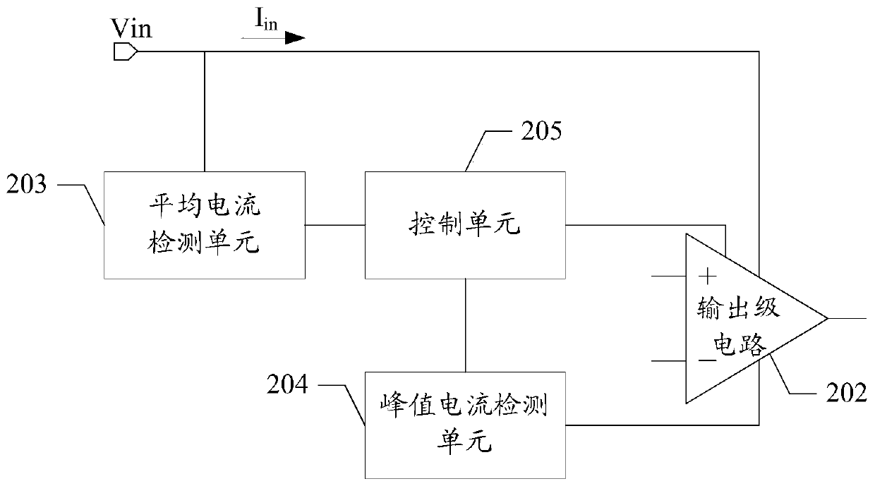
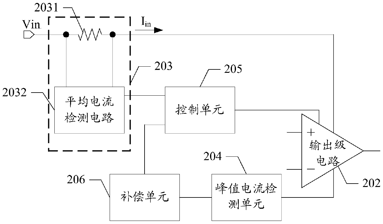
[0029] In the embodiment of the present invention, an average current detection unit is set at the power input end of the chip to obtain the average input current of the chip, and a peak current detection unit is set at the output end of the output stage circuit to obtain the current of the power transistor in the output stage circuit. peak current. The average current is compared with the peak current by the control unit, and when the peak current is greater than the average current, the control unit controls the input current of the output stage circuit to decrease. Since ...


PUM


Abstract

A power supply system protection circuit comprises a chip having a current limiting protection function. The chip comprises an output level circuit with a power tube. The power supply system protection circuit comprises an average current detection unit which is coupled with a power supply input end of the chip and is suitable for obtaining an average current input to the chip; a peak current detection unit which is coupled with an output end of the chip output level circuit and is suitable for detecting the peak current of the power tube in the output level circuit; and a control unit, wherein a first input end is coupled with the average current detection unit, a second input end is coupled with the peak current detection unit, an output end is coupled with the output level circuit, and the control unit is suitable for reducing the input circuit of the output level circuit so as to reduce the average current output by a power supply when the peak current of the power tube is larger than the average current. By adopting the power supply system protection circuit, the chip and the power supply can be more effectively protected.

Description

technical field [0001] The invention relates to the field of circuit protection, in particular to a power supply system protection circuit. Background technique [0002] The protection circuit inside the chip refers to the detection of certain parameter indicators inside the chip through a certain device or circuit structure, so as to protect the chip when the chip parameters are abnormal. [0003] The power tube is the core device inside the chip. It is a high-power switching device. If the current on the power tube is large, the temperature of the power tube will rise, and it may burn out, that is, the overcurrent will cause the power tube to heat up. damage. At the same time, when the current on the power tube is large, or the load is short-circuited due to other reasons, the power tube will draw a large current from the power supply end, resulting in abnormal function of the internal or external expansion circuit of the chip and a series of safety hazards caused by it. ...

Claims


Application Information

Patent Timeline
Patent Type & Authority Patents(China)
IPC IPC(8): H02M1/32
Inventor 袁俊孙佳云李浩沅
Owner SHANGHAI EASTSOFT MICROELECTRONICS
Features
  • R&D
  • Intellectual Property
  • Life Sciences
  • Materials
  • Tech Scout
  • Unparalleled Data Quality
  • Higher Quality Content
  • 60% Fewer Hallucinations
Learn More