
Power control method and device

A power control and power technology, applied in the field of communication, can solve the problems of power control divergence, low throughput, adjacent cell interference, etc.

Active Publication Date: 2016-10-05
CHENGDU TD TECH LTD
View PDF4 Cites 5 Cited by
  • Summary
  • Abstract
  • Description
  • Claims
  • Application Information

AI Technical Summary

Problems solved by technology

[0004] However, in the proximity or extreme proximity scenarios, there may be intermodulation interference between networks with different time slot ratios or Global System for Mobile Communication (GSM for short), due to the Cell-specific reference signal (Cell-specific reference signal) of neighboring cells Reference Signal, referred to as CRS) and the time-frequency domain position characteristics of SRS / DM-RS, SRS / DM-RS may not be affected by the CRS, so the initial SINR measurement obtained by SRS / DM-RS measurement The value will not be affected; however, the PUSCH demodulation is affected due to the severe interference of the CRS of the adjacent cell. Therefore, from the service appearance, the throughput and MCS are extremely low, and the residual power of the terminal is large.
However, according to the existing power control scheme, the power is adjusted according to the current MCS order of the terminal and the initial transmission BLER. The extremely close point keeps high power all the time, which causes divergence of power control and interference to adjacent cells, and even causes other terminals in this cell to fail to access the network due to too much interference

Method used


Image

  • Power control method and device
  • Power control method and device
  • Power control method and device

Examples


Embodiment Construction

[0041] In order to make the objectives, technical solutions, and advantages of the embodiments of the present invention clearer, the technical solutions in the embodiments of the present invention will be described clearly and completely in conjunction with the accompanying drawings in the embodiments of the present invention. Obviously, the described embodiments It is a part of the embodiments of the present invention, not all the embodiments. Based on the embodiments of the present invention, all other embodiments obtained by those of ordinary skill in the art without creative work shall fall within the protection scope of the present invention.

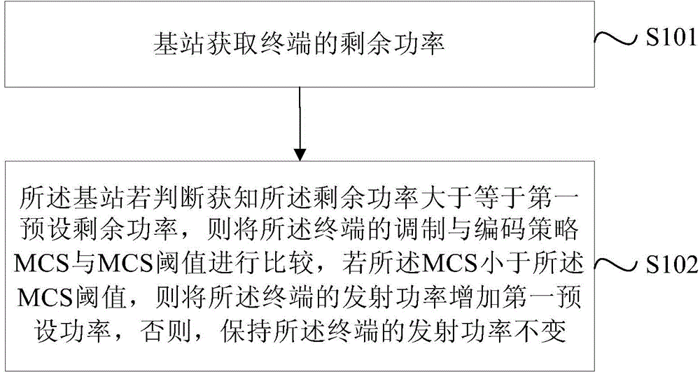
[0042] figure 1 It is a schematic flowchart of Embodiment 1 of the power control method of the present invention, such as figure 1 As shown, the method of this embodiment may include:

[0043] S101. The base station obtains the remaining power of the terminal.

[0044] S102. If the base station determines that the remaining power is grea...


PUM


Abstract

Embodiments of the present invention provide a power control method and a device. The method comprises the steps of acquiring the residual power of a terminal by a base station; on the condition that the base station judges the residual power is larger than or equal to a first preset residual power, comparing the modulating and coding scheme (MCS) of the terminal with a MCS threshold value; on the condition that the MCS is smaller than the MCS threshold value, increasing the transmitting power of the terminal by a first preset power; otherwise, keeping the transmitting power of the terminal to be unchanged. The MCS threshold value is smaller than the highest order of the MCS. Therefore, the inter-cell interference caused by the power control divergence of a near-point terminal can be reduced. The fairness of terminals in the same cell or in neighboring cells can be ensured, so that terminals in the same cell or in neighboring cells can be successfully accessed to the internet.

Description

Technical field [0001] The embodiments of the present invention relate to communication technology, and in particular, to a power control method and device. Background technique [0002] In the current Long Term Evolution (LTE) system, the power control mechanism mainly depends on the two signal to interference plus noise ratio (Signal to Interference plus Noise Ratio, SINR) measurement values ​​(ie, the initial SINR measurement value and adjustment SINR measurement). Wherein, the initial SINR measurement value is obtained based on the channel sounding reference signal (Sounding Reference Signal, SRS) / demodulation reference signal (DM-RS) measurement value; the adjusted SINR measurement value is based on the physical uplink The initial transmission Block Error Ratio (BLER) of the Physical Uplink Shared Channel (PUSCH) is obtained after adjusting the initial SINR measurement value. [0003] When the terminal is in the very near point and / or near point scenario of the serving cell,...

Claims


Application Information

Patent Timeline
Patent Type & Authority Applications(China)
IPC IPC(8): H04W52/18H04W52/24
Inventor 袁慧
Owner CHENGDU TD TECH LTD
Learn More