Puncher pin mechanism with buffer function

A punch and functional technology, applied in the field of die processing, can solve the problems of easy wear, shorten the service life of the punch, and not cooling down in time, so as to reduce wear, prolong the service life and facilitate cooling

Inactive Publication Date: 2016-10-12
江苏华航威泰机器人科技有限公司
View PDF6 Cites 8 Cited by
  • Summary
  • Abstract
  • Description
  • Claims
  • Application Information

AI Technical Summary

Problems solved by technology

[0003] The purpose of the present invention is to overcome the problems of the existing punch mechanism, the contact between the punch and the workpiece is hard collision, easy to wear, and the heat is not cooled in time during punching, which shortens the service life of the punch

Method used


Image

  • Puncher pin mechanism with buffer function

Examples


Embodiment Construction

[0015] The present invention will be further described below in conjunction with the accompanying drawings. The following examples are only used to illustrate the technical solution of the present invention more clearly, but not to limit the protection scope of the present invention.

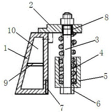
[0016] Such as figure 1 As shown, the punch mechanism with cushioning function of the present invention includes a support seat 1 with a right-angled trapezoidal cross section, a stamping plate 2 is fixed on the upper side of the support seat 1, and a stamping rod runs vertically downward on the stamping plate 2 3. The outer wall of the punching rod 3 located below the punching plate 2 is sleeved with a buffer spring 4 , the outer wall of the buffer spring 4 is sleeved with a spring protection sleeve 5 , and the lower end of the punching rod 3 is screwed with a punch 6 , the twisted punch 6 is easy to replace, and the right-angle side of the support seat 1 on the side of the punch 6 is provided...


PUM


Abstract

The invention discloses a puncher pin mechanism with a buffer function. The puncher pin mechanism comprises a supporting seat with the section in a right trapezoid shape. A punching plate is fixed to the upper side of the supporting seat. A punching rod penetrates the punching plate vertically downwards. The position, located below the punching plate, of the outer wall of the punching rod is sleeved with a buffer spring. The outer wall of the buffer spring is sleeved with a spring protection sleeve. The lower end of the punching rod is connected with a puncher pin in a screwing manner. A cooling fan mounted in an embedded manner is arranged on the right angle side, on one side of the puncher pin, of the supporting seat. An air outlet of the cooling fan right faces the puncher pin. According to the puncher pin mechanism with the buffer function, the spring buffer function is achieved through punching, the cooling fan is arranged at the position, right facing the puncher pin, of the supporting seat, and therefore air flows fast, cooling is facilitated, abrasion of the puncher pin is relieved, the service life is prolonged, the structure is simple, implementation is easy, and good application prospects are achieved.

Description

technical field [0001] The invention relates to a punch mechanism with a buffer function, which belongs to the technical field of die processing. Background technique [0002] The punch mechanism is used for high-pressure punching of the workpiece and is a key component on the punching machine. At present, in the punch mechanism on the market, the contact between the punch and the workpiece is hard collision, the punch is easy to wear and needs to be replaced frequently, which reduces the work efficiency and virtually increases the stamping cost of the workpiece. Moreover, the punch is in the stamping process. The temperature is high, if the heat is not cooled in time, it will accelerate the damage of the punch and further shorten its service life. Contents of the invention [0003] The purpose of the present invention is to overcome the problems of the existing punch mechanism, the contact between the punch and the workpiece is hard collision, easy to wear, and the servi...

Claims


Application Information

Patent Timeline
Patent Type & Authority Applications(China)
IPC IPC(8): B21D37/10B21D37/16
CPCB21D37/10B21D37/16
Inventor 钱进
Owner 江苏华航威泰机器人科技有限公司
Why Eureka
Try Eureka