Hydraulic system with buffer function

A hydraulic system and functional technology, applied to fluid pressure actuation system components, fluid pressure actuation devices, servo motors, etc., can solve the problems of difficult replacement of throttle orifices, easy jamming, long length, etc., and achieve good The effect of commercial prospects, cost reduction, and convenient operation

Inactive Publication Date: 2013-12-25
CHANGZHOU HYDRAULIC COMPLETE EQUIP
View PDF0 Cites 8 Cited by
  • Summary
  • Abstract
  • Description
  • Claims
  • Application Information

AI Technical Summary

Problems solved by technology

[0002] The buffer structure of the existing fast gate hydraulic hoist is a mechanical buffer structure, which is composed of a buffer sleeve, a buffer ring, and a throttling orifice plate. However, this buffer form has the following disadvantages: first, the buffer sleeve is thin Wall-shaped parts, and the length is long, difficult to process, and easy to deform; second, there is a transition fit between the buffer sleeve and the buffer ring. Because of the deformation of the buffer sleeve, it is easy for the buffer sleeve to enter the buffer ring when the cylinder is running. It is stuck, so that the running time of the oil cylinder is too long; third, the throttle orifice is installed on the lower end cover of the oil cylinder, and the buffer function of the throttle orifice cannot be tested during the test of the oil cylinder, and it can only be assembled on site. After the oil cylinder is installed in place, it is more difficult to replace the throttle orifice

Method used


Image

  • Hydraulic system with buffer function

Examples


Embodiment Construction

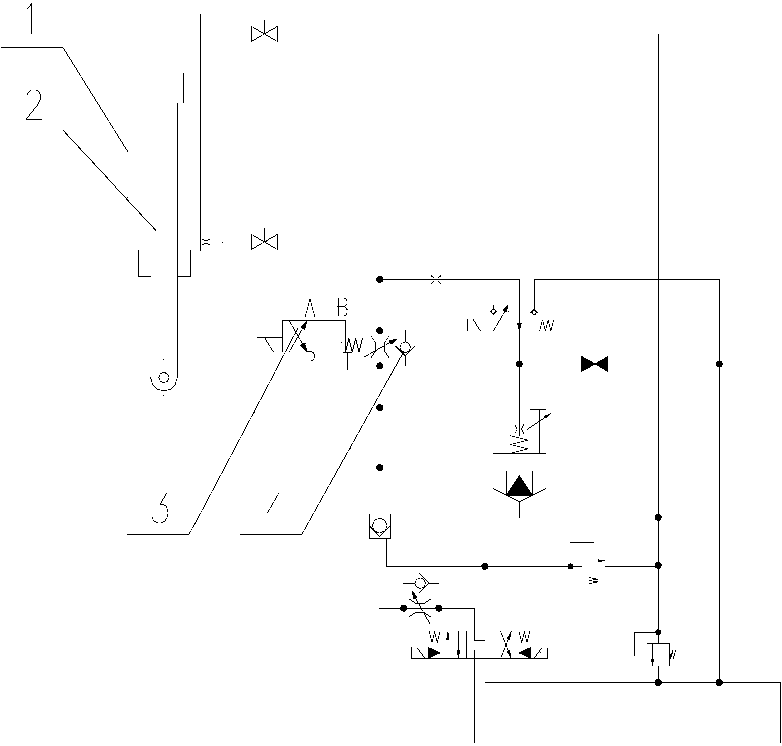
[0010] The present invention is described in further detail now in conjunction with accompanying drawing. These drawings are all simplified schematic diagrams, which only illustrate the basic structure of the present invention in a schematic manner, so they only show the configurations related to the present invention.

[0011] As shown in Figure 1, a hydraulic system with a buffer function includes a buffer cylinder 1, a piston rod 2 and a cartridge valve system. The oil port of the valve system is connected, and a reversing valve 3 and a one-way throttle valve 4 are installed on the control oil circuit between the buffer cylinder 1 and the cartridge valve system, and the reversing valve 3 and the one-way throttle valve 4 parallel settings.

[0012] The reversing valve 3 is an electromagnetic reversing valve. When the piston rod 2 stretches out, the electromagnet in the reversing valve 3 is energized. When the piston rod 2 moves to the set buffer position, the reversing valv...


PUM


Abstract

The invention relates to a hydraulic system with a buffer function. The hydraulic system comprises a buffer cylinder, a piston rod and a cartridge valve system, wherein the piston rod is arranged in the buffer cylinder; the buffer cylinder is connected with an oil port of the cartridge valve system through an oil pipe; a control oil path between the buffer cylinder and the cartridge valve system is provided with a reversing valve and a one-way throttle valve; the reversing valve and the one-way throttle valve are connected in parallel. Since the hydraulic system with the buffer function is provided with the reversing valve and the one-way throttle valve, the reversing valve and the one-way throttle valve can achieve the purpose of buffer by controlling the throughput of hydraulic oil in the buffer cylinder; the hydraulic system with the buffer function has the advantages of simple structure, convenience in operation, flexibility in adjustment, safety, reliability and reduced cost and has good business prospect.

Description

technical field [0001] The invention relates to the field of hydraulic systems, in particular to a hydraulic system with a buffer function for a fast gate hydraulic hoist. Background technique [0002] The buffer structure of the existing fast gate hydraulic hoist is a mechanical buffer structure, which is composed of a buffer sleeve, a buffer ring, and a throttling orifice plate. However, this buffer form has the following disadvantages: first, the buffer sleeve is thin Wall-shaped parts, and the length is long, difficult to process, and easy to deform; second, there is a transition fit between the buffer sleeve and the buffer ring. Because of the deformation of the buffer sleeve, it is easy for the buffer sleeve to enter the buffer ring when the cylinder is running. It is stuck, so that the running time of the oil cylinder is too long; third, the throttle orifice is installed on the lower end cover of the oil cylinder, and the buffer function of the throttle orifice cannot...

Claims


Application Information

Patent Timeline
Patent Type & Authority Applications(China)
IPC IPC(8): F15B11/02F15B21/00
Inventor 丁玲徐艳蔡云龙严强
Owner CHANGZHOU HYDRAULIC COMPLETE EQUIP
Why Eureka
Try Eureka