Floating clamp

A floating fixture technology, applied in the direction of clamping, manufacturing tools, support, etc., can solve the problems of force concentration, irregular shape, waste products, etc., and achieve the effect of reducing force concentration and deformation

Active Publication Date: 2016-10-12
HENAN PINGGAO ELECTRIC +2
View PDF6 Cites 15 Cited by
  • Summary
  • Abstract
  • Description
  • Claims
  • Application Information

AI Technical Summary

Problems solved by technology

[0003] At present, a large number of cast special-shaped parts are used in high-pressure products. Special-shaped parts refer to parts with irregular shapes. When processing special-shaped parts, general-purpose fixtures are usually used for clamping and clamping. The clamping force on the general-purpose fixture passes through the positioning fulcrum Or the positioning surface acts on the special-shaped parts. Due to the irregular shape of the special-shaped

Method used


Image

  • Floating clamp
  • Floating clamp
  • Floating clamp

Examples


Embodiment Construction

[0029] Embodiments of the present invention will be further described below in conjunction with the accompanying drawings.

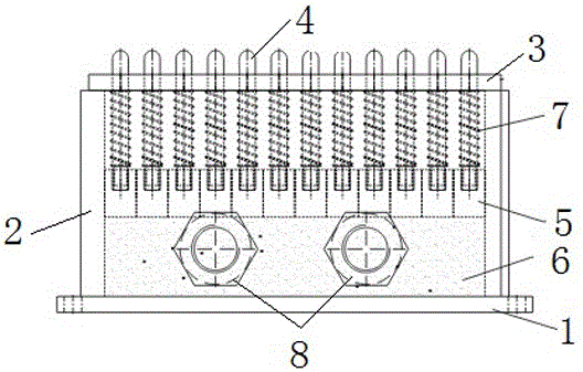
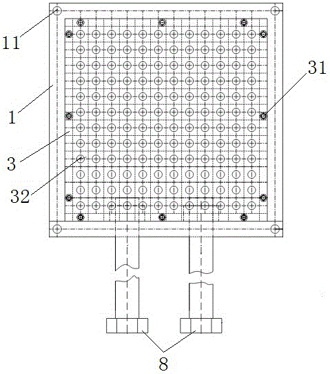
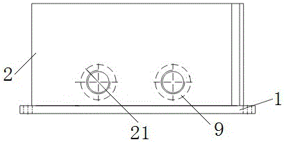
[0030] A specific embodiment of a floating fixture of the present invention, such as Figure 1 to Figure 2 As shown, it includes a pressure box and a plurality of axially floating ejector rods 4 . Such as image 3 and Figure 4 As shown, the pressure box body includes a base plate 1, a side wall plate 2 and a cover plate 3. The lower end surface of the side wall plate is welded on the base plate, and the outer surface of the base plate is the reference plane. Such as Figure 5 As shown, the base plate 1 is provided with a connecting hole 11 fixedly connected with the workbench on the periphery of the side wall 2, and the upper end surface of the side wall 2 is provided with first threaded holes 22 evenly distributed. 2. The four side panels are welded sequentially from the beginning to the end, and the welds between adjacent side panels are fillet we...


PUM


Abstract

The invention relates to a floating clamp. The floating clamp comprises a pressure box, wherein a plurality of jacking rods floating along an axial direction and used for jacking a specially-shaped part are assembled on at least one side surface except a reference surface, of the pressure box in a manner of guide sealing; one end of each jacking rod is located in the pressure box, and the other end of the jacking rod stretches out of the pressure box; working mediums used for pushing the jacking rods to axially float are arranged in the pressure box; and a space adjustment mechanism used for adjusting the size of a space where the working mediums are located is arranged on the pressure box. The space where the working mediums are located is reduced through the space adjustment mechanism, so that the working mediums push the jacking rods to axially float to jack the specially-shaped part; acting forces on the jacking rods are the same according to a hydraulic principle; the plurality of jacking rods form a plurality of equal-force fulcrums and the equal-force fulcrums act on different parts of the specially-shaped part, thus the acting forces acting on the specially-shaped part are effectively dispersed, the stress concentration of the specially-shaped part is reduced, and the deformation amount of the specially-shaped part is reduced.

Description

technical field [0001] The invention belongs to the field of clamps for mechanical processing, and in particular relates to a floating clamp. Background technique [0002] The fixture is an important auxiliary device in machining. It is used to fix the object to be processed so that it is in the correct processing position during the machining process, so as to ensure that it is accurately processed by the processing tool. [0003] At present, a large number of cast special-shaped parts are used in high-pressure products. Special-shaped parts refer to parts with irregular shapes. When processing special-shaped parts, general-purpose fixtures are usually used for clamping and clamping. The clamping force on the general-purpose fixture passes through the positioning fulcrum Or the positioning surface acts on the special-shaped parts. Due to the irregular shape of the special-shaped parts, the clamping force of the universal fixture can only act on a certain point or a certain ...

Claims


Application Information

Patent Timeline
IPC IPC(8): B23Q3/06
CPCB23Q3/062
Inventor 张全民刘拥军胡延伟刘作庆贾广涛王晓贞武松李静瑞刘德源
Owner HENAN PINGGAO ELECTRIC
Why Eureka
Try Eureka