Bidirectional mechanical transformer

A converter and mechanical technology, applied in portable drilling rigs, portable motorized devices, manufacturing tools, etc., can solve problems such as the trouble of replacing bit bits, easy scattering and loss of parts, and difficulty in ensuring the integrity of screwdrivers, etc., and achieves simple and compact structure, Convenient reversing and easy operation

Active Publication Date: 2016-10-12
HANGZHOU GREAT STAR TOOLS +1
View PDF6 Cites 4 Cited by
  • Summary
  • Abstract
  • Description
  • Claims
  • Application Information

AI Technical Summary

Problems solved by technology

It can be seen that it is very inconvenient for the mechanical converter of the invention to change the direction of the main shaft
For multi-purpose screwdrivers with replaceable bit heads, it is very troublesome to change the bit back and forth at both ends of the spindle
In addition, it must be ensured that the handle can be easily detached from the spindle, which means that the integrity of the entire screwdriver itself is not easy to guarantee, and parts are easily scattered and lost

Method used


Image

  • Bidirectional mechanical transformer
  • Bidirectional mechanical transformer
  • Bidirectional mechanical transformer

Examples


Embodiment 1

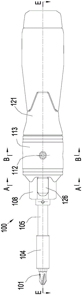
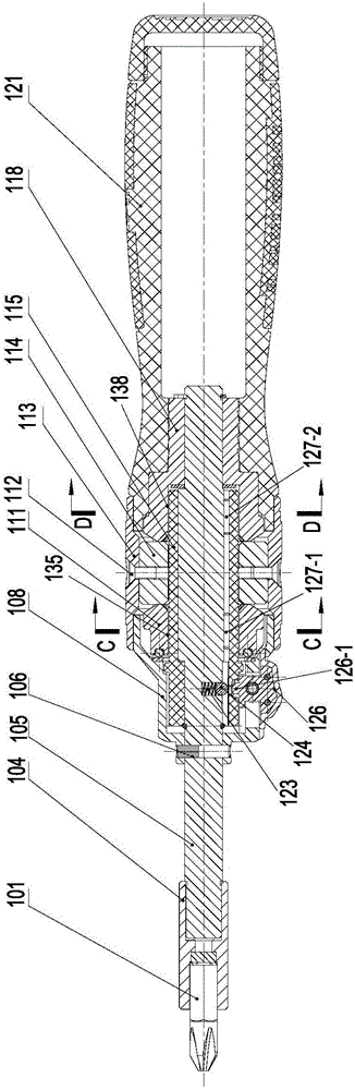
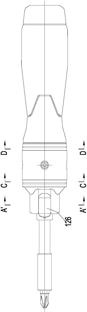
[0066] refer to figure 1 and figure 2 , a preferred embodiment is to apply the bidirectional mechanical converter of the present invention to a manual screwdriver 100, the screwdriver 100 is passed such as Figure 4 The transmission mechanism 120 shown realizes bidirectional double-speed transmission. The transmission mechanism 120 includes Figure 4 The transmission device 130 and the reversing device 110 shown can realize the switching of the rotation direction of the main shaft. Figure 5 and Figure 6 The structure and installation relationship of the transmission device 130 and the reversing device 110 are shown. The "two-way double-speed transmission" or "two-way transmission" of the present invention is relative to the input, that is, the handle is used as a rotating device, and its input force can be in any direction clockwise or counterclockwise. can be used effectively. The "reversible" in the present invention means that the output rotation direction of the m...

Embodiment 2

[0110] This embodiment is similar to the first embodiment, except that the reversing device 110 in the first embodiment is replaced by Figure 11C , 11D and Figure 12C , 12D The ratchet-pawl reversing device shown. A pawl seat is provided on the main shaft 105, and two reverse swingable pawls are arranged symmetrically on the pawl seat, namely Figure 11D and 12D Corresponding pawl seat 223 and pawls 224a and 224b of driving wheel 118, Figure 11C and 12C The center corresponds to the pawl seat 213 and the pawls 214 a and 214 b of the driven wheel 111 . There is an opening on the reversing element 215, and the two ends of the opening can push the ratchet to change the working position of the ratchet (that is, to set the rotation direction of the main shaft). Figure 11C and 12C Among them, the two ends of the opening of the reversing element 215 are 216a and 216b, Figure 11D and 12D Two ends of the middle opening are 226a and 226b. The inner circular surfaces of t...

Embodiment 3

[0118] This embodiment is similar to the first embodiment, except that the reversing device 110 in the first embodiment is replaced by Figure 13C , 13D and Figure 14C , 14D The brake pad type reversing device shown. Parallel grooves are slotted on both sides of the axis on the main shaft 105, and brake blocks are arranged in the grooves, that is, Figure 13D and Figure 14D corresponding to the brake blocks 324a and 324b of the driving wheel 118, Figure 13C and Figure 14C Corresponding to the brake blocks 314a and 314b of the driven wheel 111 . The outer end surfaces of the brake blocks 314a and 314b are inclined surfaces, and the two inclined surfaces face each other in a V shape. The reversing element 315 has an upper opening, and the opening end can push the outer end surface of the brake block to make the brake block expand and contract in the groove, thereby changing the working position of the brake block (that is, setting the rotation direction of the main sh...


PUM


Abstract

The invention discloses a bidirectional mechanical transformer. The bidirectional mechanical transformer comprises a spindle, a transmission mechanism and a rotating device for inputting torque. The transmission mechanism comprises a transmission device and a reversing device which are connected with each other. A rotating shaft of the rotating device and the spindle are coaxial. The rotating device is connected with the transmission device. By means of the transmission device, the torque is transmitted to the spindle to be output in a preset direction no matter what the rotating direction of the rotating device is. By means of the reversing device, the preset direction can be transformed. The bidirectional mechanical transformer is simple and compact in structure; bidirectional movement of a drive device can be effectively utilized, and the rotating direction of the output shaft can be transformed conveniently according to needs; and operation is easy and convenient.

Description

[0001] This application is a divisional application of the following applications: filing date: September 1, 2011; application number: 201110270810.5; invention name: "two-way mechanical converter". technical field [0002] The present invention relates to hand tools, and more particularly to a mechanical converter that effectively utilizes the bidirectional movement of a driving device. Background technique [0003] In the use of manual tools such as screwdrivers and torque wrenches, the movement of the hand in the direction of rotation has a certain limit, and it will not continue in one direction. In this type of tool, the rotation axis of the handle is coaxial with the main shaft, and it is generally used as follows: first, the handle is turned by hand in a desired direction (such as tightening or loosening a screw), and then the hand is reversed. Rotate to reposition the tool for the next cycle. In the second part of the above cycle, the reverse rotation of the hand ca...

Claims


Application Information

Patent Timeline
Patent Type & Authority Applications(China)
IPC IPC(8): B25B23/00B25B15/00B25B13/00B23B45/06B25F5/00
CPCB23B45/06B25B13/00B25B15/00B25B23/00B25F5/00
Inventor 王伟毅
Owner HANGZHOU GREAT STAR TOOLS
Why Eureka
Try Eureka