
Assembly tooling for annular net cabinet
A technology for assembling tooling and ring network cabinets, which is applied to assembly machines, workbenches, manufacturing tools, etc., can solve the problems of inability to realize the rotating production line of the air box, unstable support of the air box, and unfavorable assembly efficiency of the ring network cabinet, so as to avoid The effect of reducing operating efficiency, avoiding inconvenient operation, and avoiding waste of working hours
Patent Information
- Authority / Receiving Office
- CN · China
- Patent Type
- Applications(China)
- Current Assignee / Owner
- Publication Date
- 2016-10-12
- Estimated Expiration
- Not applicable · inactive patent
Smart Images
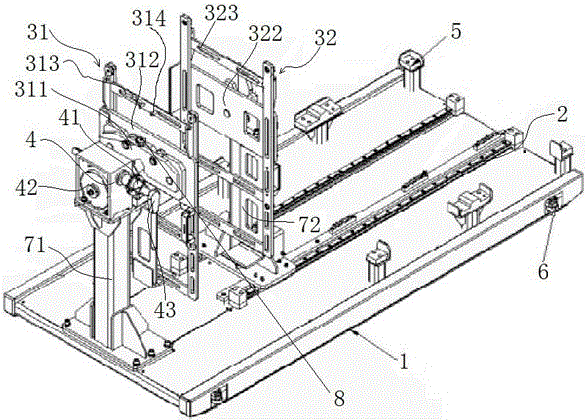
Figure 1
Abstract
Description
technical field
[0001] The invention relates to an assembly tool for a ring network cabinet. Background technique
[0002] The gas box is used to set various cables, conductive bars, insulators, etc. required for power distribution. It is the core component of the gas-insulated metal-enclosed switchgear. Assemble cables, conductive bars, insulators and other parts in the box. After the internal parts of the air box are installed, close the air box to complete the assembly of the ring main unit. Since the air box has an irregular shape with a protruding structure on the bottom surface, it is difficult to place the air box stably on the reference plane when it is in a normal vertical position, and the air box must be supported by a bracket. Simultaneously, because the upper and lower sides of the gas box have parts to be assembled, in order to facilitate assembly, the gas box needs to be rotated in real time during the assembly process so that the surface to be assembled face...
Examples
Embodiment Construction
[0019] Embodiment of assembly tooling for ring main unit:
[0020] The specific structure of the assembly tooling for the ring network cabinet is as follows: figure 1 As shown, it includes a base 1 and a stand arranged on the base 1. The stand includes a front column 71 and a rear column 72 which are fixedly arranged on the base 1 and arranged at intervals along the front-to-back direction, and are respectively rotatably mounted on the front column 71 and the rear column. The front swivel clamp 31 and the rear swivel clamp 32 on the column 72 . The front column 71 is also provided with a drive mechanism 4 for driving the front rotary fixture 31 to rotate. The front rotary fixture 31 is an active rotary fixture, and the rear rotary fixture 32 is a driven rotary fixture that is driven to rotate by an air box installed between the front and rear rotary fixtures. . The base 1 extends along the front-to-back direction, and two racks 2 extending along the front-to-back direction a...