
Plastic mold with counting function

A technology of plastic molds and functions, applied in the field of plastic molds with counting function, can solve the problems of increasing the workload of workers, low efficiency, and error-prone total output, so as to avoid statistical errors and improve labor efficiency.

Inactive Publication Date: 2016-10-12
苏州天朋精密元器件有限公司
View PDF4 Cites 3 Cited by
  • Summary
  • Abstract
  • Description
  • Claims
  • Application Information

AI Technical Summary

Problems solved by technology

[0004] In the current injection molding process, the total amount of injection molded parts depends on manual statistics, which is inefficient and increases the workload of workers, and the statistics of the total output are prone to errors

Method used


Image

  • Plastic mold with counting function

Examples


Embodiment Construction

[0016] The specific implementation manners of the present invention will be further described in detail below in conjunction with the accompanying drawings and embodiments. The following examples are used to illustrate the present invention, but are not intended to limit the scope of the present invention.

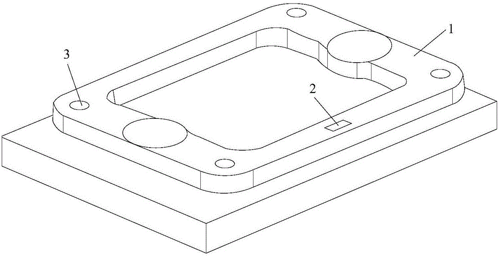
[0017] see figure 1 , a kind of plastic mold with counting function described in a preferred embodiment of the present invention includes a die 1, a punch (not shown), a counting sensor 2 arranged on the die 1, a counting sensor 2 and a controller connect.

[0018] The counting sensor 2 is a photoelectric sensor, which counts the number of opening and closing of the upper and lower molds by blocking the light source of the photoelectric sensor through the pressing and rising of the punch. The controller includes a digital output and a display to show the number of injection molded parts. The die 1 is provided with four positioning holes 3, and the punch is provided with...


PUM


Abstract

The invention belongs to the technical field of molds and particularly relates to a plastic mold with a counting function. The plastic mold comprises a female mold, a male mold, and a counting sensor arranged on the female mold. The counting sensor is connected with a controller. By arranging the counting sensor on the female mold, statistics can be carried out on the opening and closing frequency of the upper and lower molds, thus, statistics can be carried out on the yield of an injection molding machine, tedious manual statistics is omitted, the labor efficiency is improved, and statistics errors are avoided.

Description

technical field [0001] The invention belongs to the technical field of moulds, in particular to a plastic mold with a counting function. Background technique [0002] A mold is a tool used to shape an article. This tool is composed of various parts. Different molds are composed of different parts. It mainly realizes the processing of the shape of the article through the change of the physical state of the molding material. [0003] With the rapid development of the plastics industry, plastic products are used in various fields of life and production. Injection molding is a processing method used in the mass production of certain parts with complex shapes. During injection molding, the mold is clamped on the injection molding machine. The heated and melted material is injected into the molding cavity by high pressure, cooled and formed in the cavity, then the upper and lower molds are separated, and the product is ejected from the cavity through the ejector system to leave th...

Claims


Application Information

Patent Timeline
IPC IPC(8): B29C45/26B29C45/76
CPCB29C45/26B29C45/76
Inventor 付朝
Owner 苏州天朋精密元器件有限公司
Learn More