Supercharge Your Innovation With Domain-Expert AI Agents!

Automatic parachute ejection special control circuit of multi-rotor-wing unmanned aerial vehicle

A multi-rotor UAV and parachute technology, applied in the field of circuits, can solve the problems of injury to people and objects, and the damage of aircraft falling from high altitude, so as to achieve the effect of protecting the safety of the machine

Active Publication Date: 2016-10-12
苏州光之翼智能科技有限公司
View PDF6 Cites 0 Cited by
  • Summary
  • Abstract
  • Description
  • Claims
  • Application Information

AI Technical Summary

Problems solved by technology

[0002] With the gradual popularization of multi-rotor drones, when the airborne safety parachute of the drone is opened is also a key point in this technical field, but the control of the general parachute is still carried out by the flight controller of the drone. To control, when the flight controller fails, the parachute cannot be opened, which will cause the aircraft to fall from high altitude and be damaged, or even injure people and things

Method used


Image

  • Automatic parachute ejection special control circuit of multi-rotor-wing unmanned aerial vehicle

Examples


Embodiment Construction

[0014] The present invention will be described in detail below with reference to the accompanying drawings and in combination with embodiments.

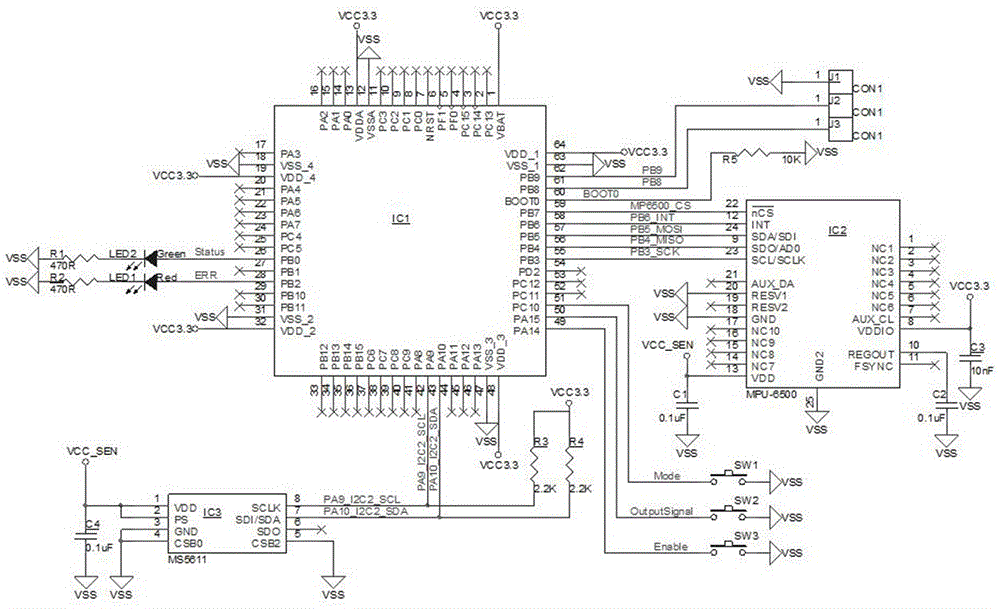
[0015] As shown in Figure 1, a multi-rotor UAV automatic parachute control circuit, including 3 chips: main control chip IC1, gyroscope accelerometer IC2, barometer IC3, 5 resistors R1, R2, R3, R4 , R5, 4 capacitors C1, C2, C3, C4, 2 light-emitting diodes LED1, LED2 and 3 connectors J1, J2, J3, the main control chip IC1 through 55, 56, 57, 58, 59 five SPI interface signals are connected with the gyroscope accelerometer IC2, the main control chip IC1 is connected with the barometer IC3 through the two I2C interface signals 42 and 43 of the chip, and the main control chip IC1 is connected with the barometer IC3 respectively through The 28 pins and 26 pins of the chip are connected to the light-emitting diodes LED1 and LED2, and the light-emitting diodes LED1 and LED2 are respectively connected to the resistor R2 and the resistor R1. P...


PUM


Abstract

The invention discloses an automatic parachute ejection special control circuit of a multi-rotor-wing unmanned aerial vehicle. The automatic parachute ejection special control circuit comprises a power supply, three chips including main control chips IC1, a gyroscope accelerometer IC2, a barometer IC3, five resistors including a resistor R1, a resistor R2, a resistor R3, a resistor R4 and a resistor R5, four capacitors including a capacitor C1, a capacitor C2, a capacitor C3 and a capacitor C4, two light-emitting diodes including a light-emitting diode LED1 and a light-emitting diode LED2, and three connectors including a connector J1, a connector J2 and a connector J3; the main control chips IC1 are connected with the gyroscope accelerometer IC2 through five SPI (Serial Peripheral Interface) signals 55, 56, 57, 58 and 59 of the chip; the main control chips IC1 are connected with the barometer IC3 through two I2C interface signals 42 and 43 of the chip. With the adoption of the automatic parachute ejection special control circuit, whether tilting of normal flight or rolling in a breakdown occurring process can be accurately judged, so that a parachute opening signal is output through the connector J1 and the connector J2 when a parachute is located at the upper side, and furthermore, the parachute is opened and the safety of the machine is protected.

Description

technical field [0001] The invention relates to the field of circuits, in particular to a special control circuit for automatic parachute ejection of a multi-rotor drone. Background technique [0002] With the gradual popularization of multi-rotor drones, when the airborne safety parachute of the drone is opened is also a key point in this technical field, but the control of the general parachute is still carried out by the flight controller of the drone. To control, when the flight controller fails, the parachute cannot be opened, which will cause the aircraft to fall from a high altitude and be damaged, or even injure people or things. When the aircraft has a problem, it is the flight control that is in a state of disorder and out of control, so the parachute is useless. Contents of the invention [0003] The purpose of the present invention is to overcome the above problems existing in the prior art, and to provide a special control circuit for automatic parachute ejec...

Claims


Application Information

Patent Timeline
IPC IPC(8): B64D17/54B64D17/80
CPCB64D17/54B64D17/80B64U70/83
Inventor 冯翼王猛
Owner 苏州光之翼智能科技有限公司
Features
  • R&D
  • Intellectual Property
  • Life Sciences
  • Materials
  • Tech Scout
  • Unparalleled Data Quality
  • Higher Quality Content
  • 60% Fewer Hallucinations
Learn More